
Method of making electrodes with distributed material loading used in electrochemical cells

a technology of electrochemical cells and materials, applied in the field of electrochemical power sources, can solve the problems of insufficient address of conventional electrode manufacturing methods, affecting the mechanical flexibility of densely compacted electrodes, and reducing the mechanical flexibility of electrodes, etc., to achieve the effect of optimizing mechanical and electrochemical properties of the resulting electrode, high energy density, and long cycle li

Inactive Publication Date: 2012-12-06
WILSON GREATBATCH LTD
View PDF2 Cites 20 Cited by
  • Summary
  • Abstract
  • Description
  • Claims
  • Application Information

AI Technical Summary

Benefits of technology

The invention describes a method for making electrodes for rechargeable batteries that have distributed electrode material loading and uniform compacting pressure along their length. This results in electrodes that are mechanically flexible for winding, but still have high energy density and long cycle life when used in both primary and secondary batteries.

Problems solved by technology

One of the key challenges in order for power sources to meet such demanding applications is to make high quality electrodes used in electrochemical cells and batteries.
On the other hand, compaction generally decreases electrode's mechanical flexibility.
A densely compacted electrode is more prone to break or crack due to sharp bending of the electrode over a mandrel during winding.
Conventional electrode manufacturing methods do not adequately address this problem.
The product electrode may have desirable energy density and cyclability, but at the expense of poor mechanical flexibility.
Or, the electrodes may have desired mechanical flexibility, but they sacrifice high energy density and cyclability.

Method used


Image

  • Method of making electrodes with distributed material loading used in electrochemical cells
  • Method of making electrodes with distributed material loading used in electrochemical cells
  • Method of making electrodes with distributed material loading used in electrochemical cells

Examples


example i

[0066]A cathode powder slurry was prepared with ingredients listed in Table 1. In particular, powdered LiCoO2 was mixed with KS6 graphite as a conductive carbonaceous material, polyvinylidene fluoride (PVDF) as a binder and N-methyl-2-pyrrolidinone (NMP) as a solvent to form a slurry.

TABLE 1MaterialWeight %LiCoO291.0% PVDF3.0%KS6 Graphite6.0%NMP55% of powder weight

[0067]The slurry was thoroughly mixed by a motor-driven stirring blade for about an hour and then coated onto a 25.4 μm thick aluminum substrate with a doctor-blade. The gap between the substrate and the doctor-blade was 254 μm, which translates to a material loading of 44.8 mg / cm2 as listed in Table 2.

TABLE 2ElectrodeCoating gapLoadingMixture(μm)(mg / cm2)Example I25444.8Example II35652.8Example III45770.9

[0068]The coating was dried in air overnight and was further dried at 100° C. in an oven with vacuum for eight hours. A second coating with the same loading as the first one was made on the other, bare side of the aluminum...

example ii

[0071]A double-sided cathode coating with the slurry formulation listed in Table 1 was made the same way as in Example I, except the gap between the substrate and the doctor-blade was 356 μm. As listed in Table 2, this translates into a material loading of 52.8 mg / cm2. The coating was dried, compacted and tested for mechanical integrity in a similar manner as described in Example I. FIG. 8B shows bendability of this coating vs. coating density. The bendability onset density was about 3.55 g / cm3.

example iii

[0072]A double-sided cathode coating with the slurry formulation listed in Table 1 was made the same way as in Example I, except the gap between the substrate and the doctor-blade was 457 μm. As listed in Table 2, this translates into a material loading of 70.9 mg / cm2. The coating was dried, compacted and tested for mechanical integrity in a similar way as in Example I. FIG. 8C shows bendability of this coating vs. coating density. The bendability onset density was about 3.45 g / cm3.

[0073]FIG. 9 is a graph showing bendability onset density vs. material loadings for Examples I, II and III. The data showed that a higher bendability onset density could be obtained with lower material loading.


PUM

PropertyMeasurementUnit
weight percentaaaaaaaaaa

Abstract

A method of making electrodes with distributed material loadings used in rechargeable electrochemical cells and batteries is described. This method controls electrode material loading (mass per unit area) along the electrode's length while maintaining uniform compaction throughout the electrode. Such prepared electrode maintain sufficient mechanical flexibility for winding and are compact and robust to have high energy density and long cycle life in rechargeable cells and batteries.

Description

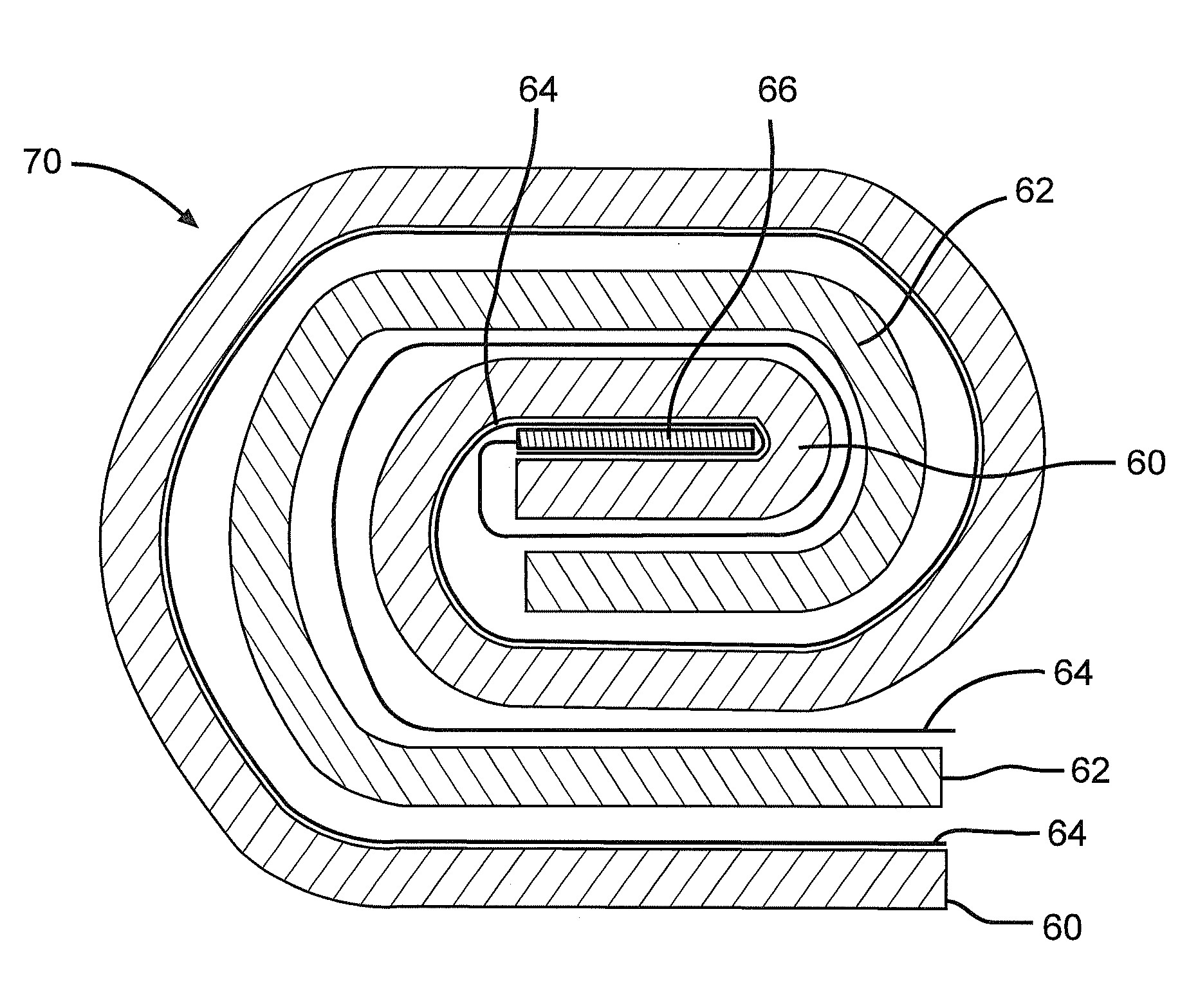
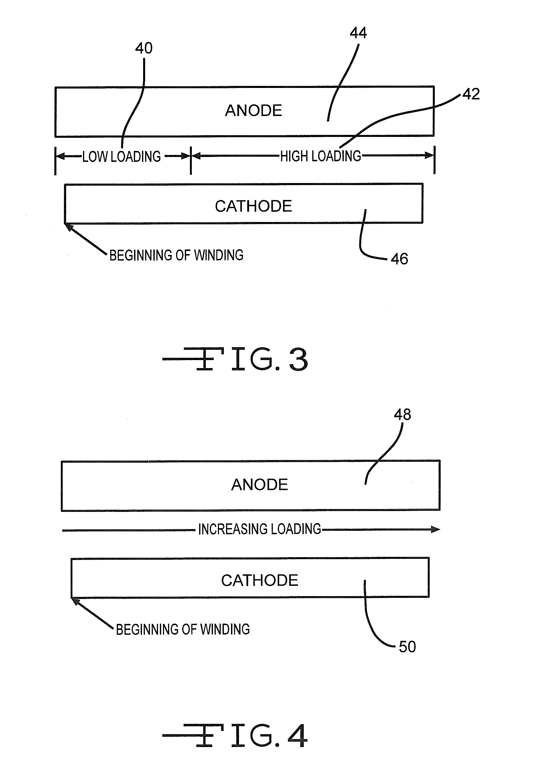
CROSS-REFERENCE TO RELATED APPLICATION[0001]This application claims priority from provisional application Ser. No. 60 / 948,535, filed Jul. 9, 2007.BACKGROUND OF THE INVENTION[0002]1. Field of the Invention[0003]This invention relates to electrochemical power sources such as cells and batteries. Specifically, this invention relates to a method of making electrodes with distributed material loadings used in rechargeable electrochemical cells or batteries. More specifically, this invention relates to a method that distributes electrode material loading along the electrode's length and uniformly compact the electrode material. Such electrodes maintain sufficient mechanical flexibility for winding, especially at the beginning of a wind where the bending curvature is the smallest. Such electrodes are compact enough to have high energy density. In rechargeable electrochemical cells, such electrodes are robust enough to have long cycle life, even under high mechanical shock and vibration con...

Claims


Application Information

Patent Timeline
Patent Type & Authority Applications(United States)
IPC IPC(8): H01M4/04H01M4/02
CPCH01M4/131H01M4/133H01M4/1391Y10T29/49115H01M4/661H01M10/0431Y02E60/122H01M4/1393Y02E60/10
Inventor XING, WEIBINGGAN, HONGTAKEUCHI, ESTHER S.
Owner WILSON GREATBATCH LTD
Learn More