Energy-saving method for gas combustion and burner thereof

a technology of energy-saving method and burner, which is applied in the direction of combustion types, household stoves or ranges, gaseous heating fuels, etc., can solve the problems of unstable combustion quality, waste of precious resources, pollution of environment, etc., and achieves improved utilization ratio, reduced gas utilization ratio, and greater firepower

Inactive Publication Date: 2012-12-06
NG KINGCHING
View PDF0 Cites 2 Cited by
  • Summary
  • Abstract
  • Description
  • Claims
  • Application Information

AI Technical Summary

Benefits of technology

[0011]The present invention adopts the gas siphoning and preheating gas drum, therefore, the gas burner can preheat the gas in the burner when the gas is supplied at low pressure, overcoming the defects as the utilization ratio of the gas is reduced after the firepower is reduced resulting from insufficient air supply when the gas is in large demand, and achieving the effects of improved utilization ratio, greater firepower, more saved energy and dramatically reduced harmful gas.
[0012]The present invention adopts the expander, therefore, when the gas burner is used, the volume of the gas is continuously expanded, and quickly expanded when the gas passes through the expander, so that the gas can be sufficiently burned, and the utilization ratio of the gas can be greatly improved.

Problems solved by technology

Their common disadvantages are as follows: when the gas is supplied at a low pressure, the burning quality is unstable when large-consumption mode is selected.
Operating personnel will be endangered by thermal radiation emitted out of flame and more than 30% of the gas discharged to the living space before being completely burnt still contains harmful substances such as hydrocarbon, methane and carbon dioxide and gas as well, so that the environment will be polluted, and the precious resources will be wasted.

Method used


Image

  • Energy-saving method for gas combustion and burner thereof
  • Energy-saving method for gas combustion and burner thereof
  • Energy-saving method for gas combustion and burner thereof

Examples


embodiment 1

[0019]An energy-saving method for gas combustion comprises the following steps:

-1) gas enters into a hearth for one time or times of compression and expansion; -2) air is introduced into the hearth and is mixed with the gas; -3) the gas is ignited, the volume of the gas and the volume of the air are rapidly expanded and compressed in the hearth, and the bonds of gas molecules are cracked; -4) the gas rotates in the hearth at a high speed and is fully combusted in a stove body to emit heat; and -5) when the gas is combusted, the gas is preheated before entering into the hearth.

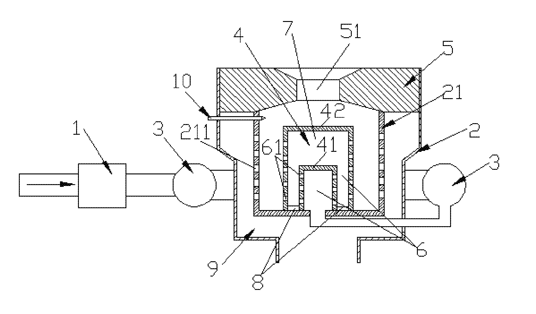
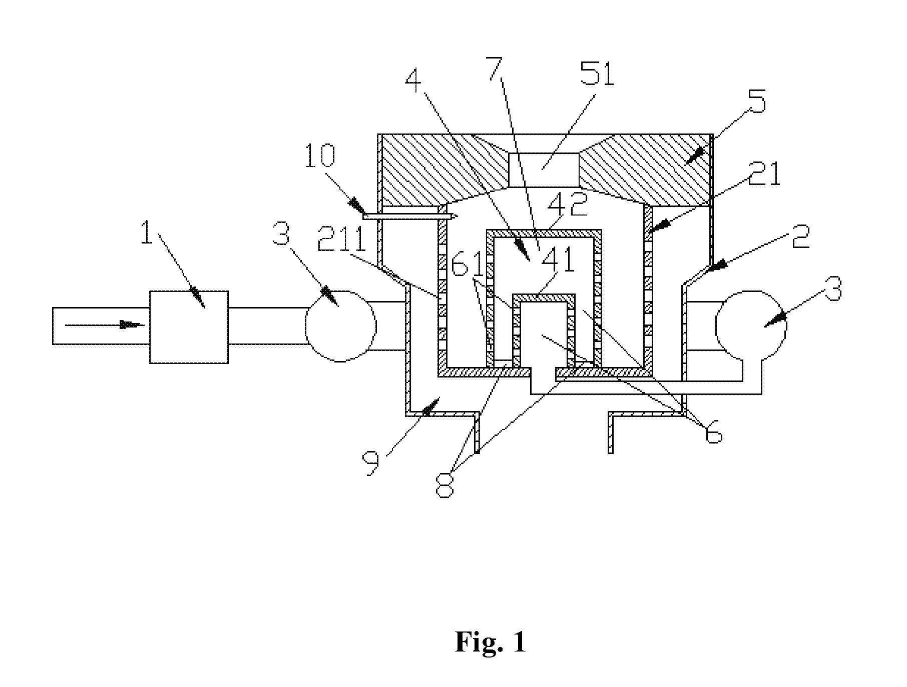
[0020]A device for implementing said energy-saving method for gas combustion is a black-hole gas burner, as shown in FIG. 1, the black-hole gas burner comprises a safety valve 1, a stove body 2 and a siphoning and preheating gas drum 3. A hearth 21 of the stove body 2 is internally provided with an expander 4 and the expander 4 is comprised of an internal expander 41 and an external expander 42. The internal / ex...

embodiment 2

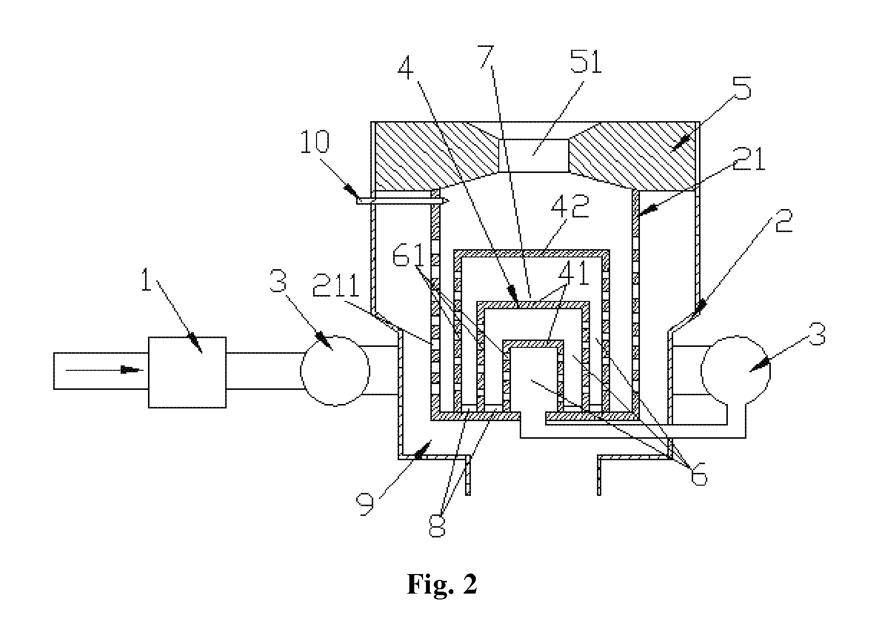
[0025]As shown in FIG. 2, the number of the internal expander 41 of the expander 4 in the black-hole gas burner of the present invention is two, and the others are the same as those in the embodiment 1.


PUM


Abstract

The present invention relates to a method and a device taking gas as fuel in industry, dining halls, power plants and the like, in particular to an energy-saving, high-efficiency and environment-friendly method and a device for gas combustion. The energy-saving method for gas combustion is characterized in that: the combustion method is that: 1. gas enters into a hearth for one time or times of compression and expansion; 2. air is introduced into the hearth and is mixed with the gas; 3. the gas is ignited, the volume of the gas and the volume of the air are rapidly expanded and compressed in the hearth, and the bonds of gas molecules are cracked; 4. the gas rotates in the hearth at a high speed, and is fully combusted in a stove body to emit heat; and 5. when the gas is combusted, the gas is preheated before entering into the hearth. The present invention further discloses a device for realizing the method. When the device is used in the said method, a series of oxidization and reduction reactions take place in all substances in the gas when the gas is continuously expanded and decomposed, and the gas is converted to extremely high heat to be emitted and is sufficiently combusted, so that the gas is combusted more sufficiently, and the energy is saved.

Description

FIELD OF THE INVENTION[0001]The present invention relates to a method and a device for utilizing gas as fuel in industry, dining halls, power plants and the like, in particular to an energy-saving method and a device for gas combustion which are high-efficiency and environment-friendly.BACKGROUND OF THE INVENTION[0002]Gas combustion process in the existing gas burner used in industry, dining halls, power plants and the like is as follows: gas is directly transported to a burner port to be burned in an open way, or the burner port is provided with some netty or multihole distributed gas dispersers for dispersedly combustion. Some gas burners are used in combination with a fan, such as CN patent number 200620175542 “vertical injecting rotational flow type high temperature-resistant combustion furnace”, and CN application number 200910128321.9 “safe energy-saving gas stove”. Their common disadvantages are as follows: when the gas is supplied at a low pressure, the burning quality is un...

Claims


Application Information

Patent Timeline
Patent Type & Authority Applications(United States)
IPC IPC(8): F23D11/44
CPCF23D14/02F24C3/085F23D14/66Y02E20/34
Inventor NG, KINGCHING
Owner NG KINGCHING
Why Eureka
Try Eureka