Disc rotor assembly for vehicle

Active Publication Date: 2012-12-13
HYUNDAI MOTOR CO LTD
View PDF5 Cites 7 Cited by
  • Summary
  • Abstract
  • Description
  • Claims
  • Application Information

AI Technical Summary

Benefits of technology

[0011]Various aspects of the present invention are directed to provide a disk rotor assembly for a vehicle having advantag

Problems solved by technology

However, a temperature of the disk rotor is raised higher than 400° C. by friction between the brake pad and the disk rotor, and heat deformation of the disk rotor may occur in this case.
Since a conve

Method used


Image

  • Disc rotor assembly for vehicle
  • Disc rotor assembly for vehicle
  • Disc rotor assembly for vehicle

Examples


Example

[0030]It should be understood that the appended drawings are not necessarily to scale, presenting a somewhat simplified representation of various features illustrative of the basic principles of the invention. The specific design features of the present invention as disclosed herein, including, for example, specific dimensions, orientations, locations, and shapes will be determined in part by the particular intended application and use environment.

[0031]In the figures, reference numbers refer to the same or equivalent parts of the present invention throughout the several figures of the drawing.

DETAILED DESCRIPTION

[0032]Reference will now be made in detail to various embodiments of the present invention(s), examples of which are illustrated in the accompanying drawings and described below. While the invention(s) will be described in conjunction with exemplary embodiments, it will be understood that the present description is not intended to limit the invention(s) to those exemplary e...


PUM


Abstract

A disk rotor assembly for a vehicle may include an adaptor adapted to be mounted on a hub and to receive torque of a wheel, a disk rotor generating a braking force, a transmitter engaging the adaptor with the disk rotor and adapted to transmit the torque received by the adaptor to the disk rotor or to transmit the braking force generated by the disk rotor to the adaptor, and engaging member for engaging the adaptor, the disk rotor, and the transmitter altogether.

Description

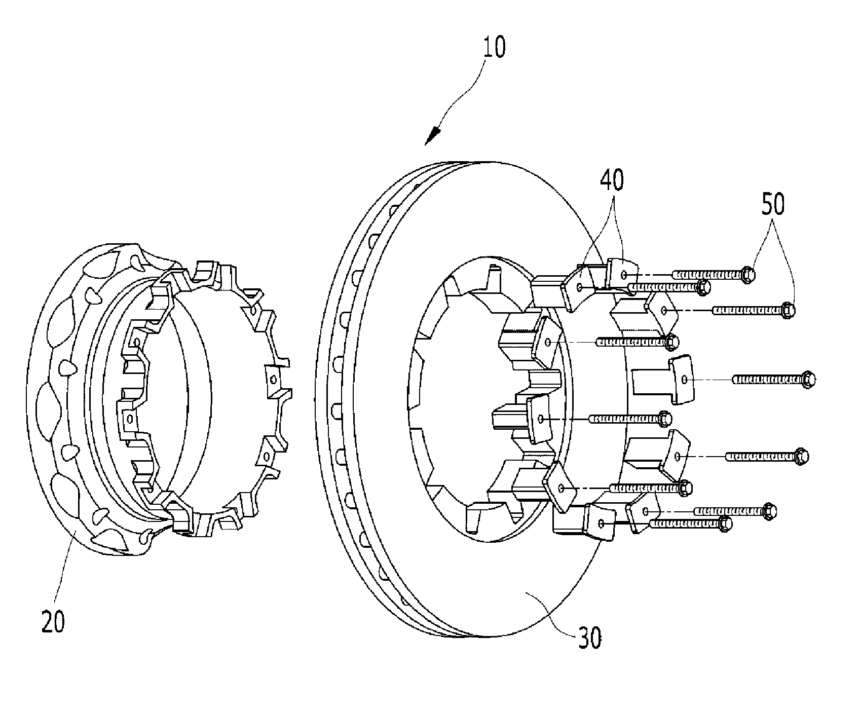
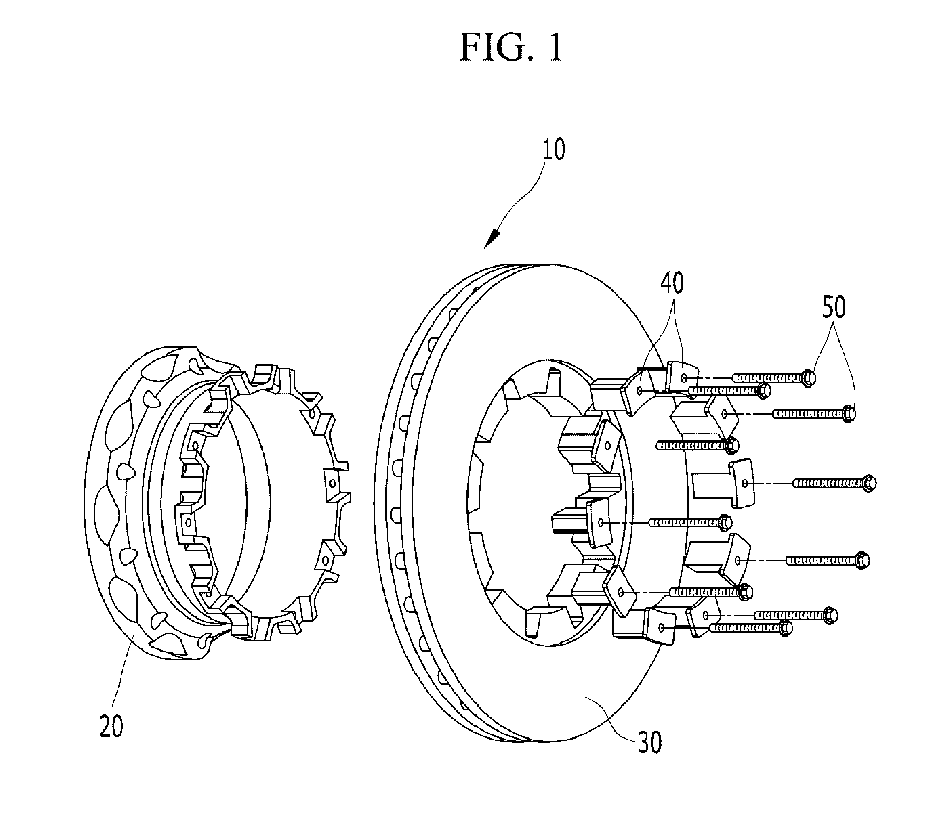
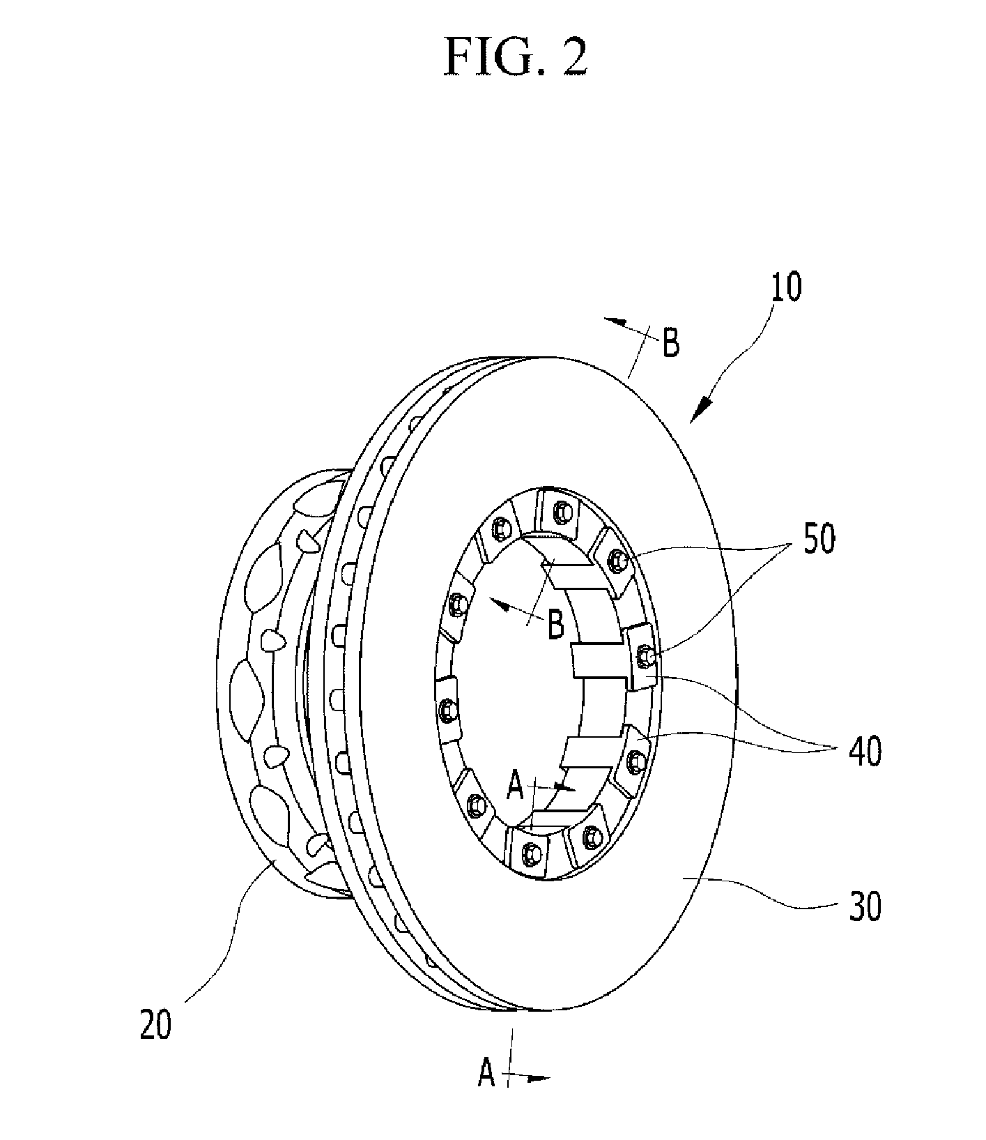
CROSS-REFERENCE TO RELATED APPLICATION[0001]The present application claims priority to Korean Patent Application No. 10-2011-0056497 filed in the Korean Intellectual Property Office on Jun. 10, 2011, the entire contents of which is incorporated herein for all purposes by this reference.BACKGROUND OF THE INVENTION[0002]1. Field of the Invention[0003]The present invention relates to a disk rotor assembly for a vehicle. More particularly, the present invention relates to a disk rotor assembly for a vehicle that prevents heat crack of a disk rotor by braking heat.[0004]2. Description of Related Art[0005]Generally, a braking apparatus of a vehicle converts kinetic energy into heat energy by friction so as to lower the vehicle's speed. The braking device is classified into a drum brake and a disk brake according to a shape of a rotating member rotating with a wheel and braking method.[0006]Meanwhile, the disk brake includes an adaptor, a disk rotor, and a brake pad. The adaptor is mounted...

Claims


Application Information

Patent Timeline
IPC IPC(8): F16D65/12
CPCF16D2065/1392F16D65/123F16D65/12
Inventor LEE, CHEL WON
Owner HYUNDAI MOTOR CO LTD
Why Eureka
Try Eureka