Method for detecting radar signals affected by interference

Inactive Publication Date: 2012-12-13
BELCEA JOHN +1
View PDF11 Cites 5 Cited by
  • Summary
  • Abstract
  • Description
  • Claims
  • Application Information

AI Technical Summary

Benefits of technology

[0037]Low complexity: The method has two steps, each step with a complexity O(N2) where N is the number of considered elements.
[0038]Accuracy: The method takes in consideration all characteristics of the reported presumed radar pulses as the time of reception, signal

Problems solved by technology

Therefore, the hardware reports as possible radar pulses all received signals for which the preamble cannot be decoded correctly.
This characteristic makes impossible creating a unique table of pulse widths for radar signals.
The method is also prone to frequent false detections as the width of radar pulses shorter than 2 μs cannot be measured precisely.
This operation does not improve the precision of the method, because (a) the number of pulses in a burst has a variation of at least ±2 pulses from burst to burst due to the position of the radar antenna and (b) some pulses within the burst cannot be identified if they arrive while the U-NII device is transmitting.
These methods cannot be used in an environment where interfering signals from other sources are interleaved with radar signals.
Unfortunately, a large number of radar pulses used by weather radar installations in Europe and Asia are shorter then 1 μs and the hardware does not have enough time for collecting the number of samples required for making an accurate prediction.
The method does not comply with currently approved certification requirements that the tested U-NII device should identify the testing signals by itself.
Disregarding this inconvenience, the method fails to identify radar signals if such signals are received by only one device in the network, which is frequent when the area where the network operates has dense foliage, the terrain is very irregular or is within cities canyons.
The method is not practical because the certification requirements indicate that the pulse width and pulse repetition frequency do not have predefined valu

Method used


Image

  • Method for detecting radar signals affected by interference
  • Method for detecting radar signals affected by interference
  • Method for detecting radar signals affected by interference

Examples


Example

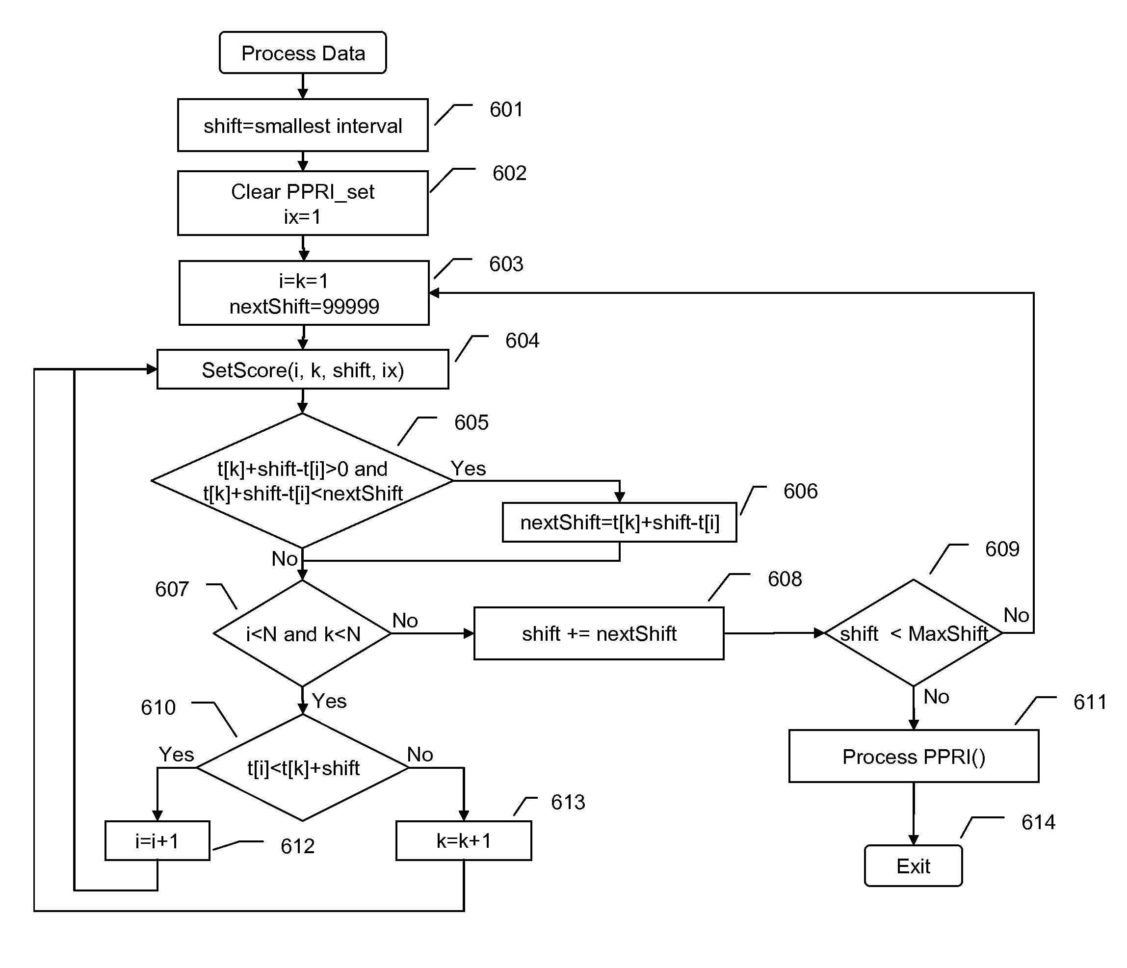
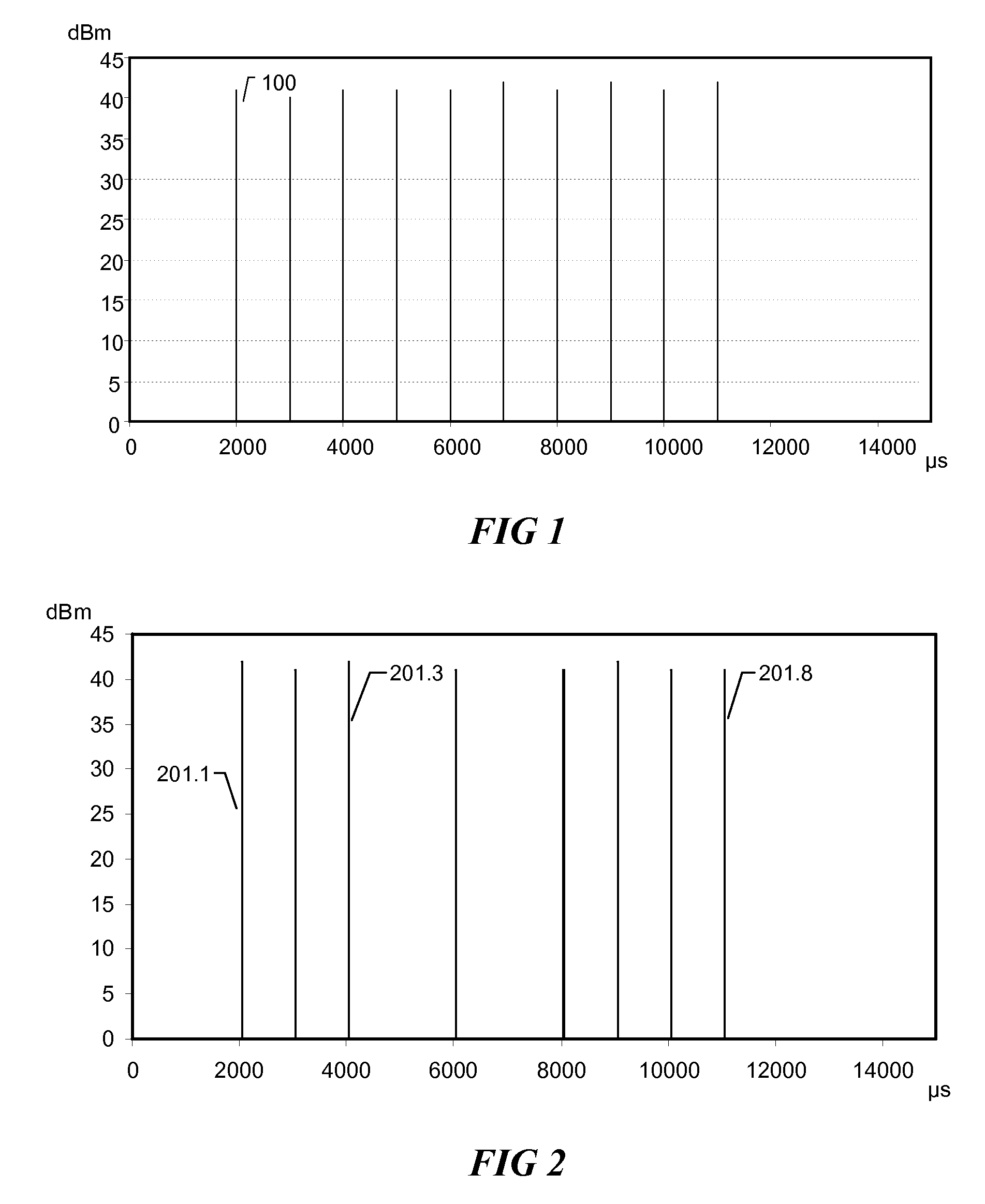
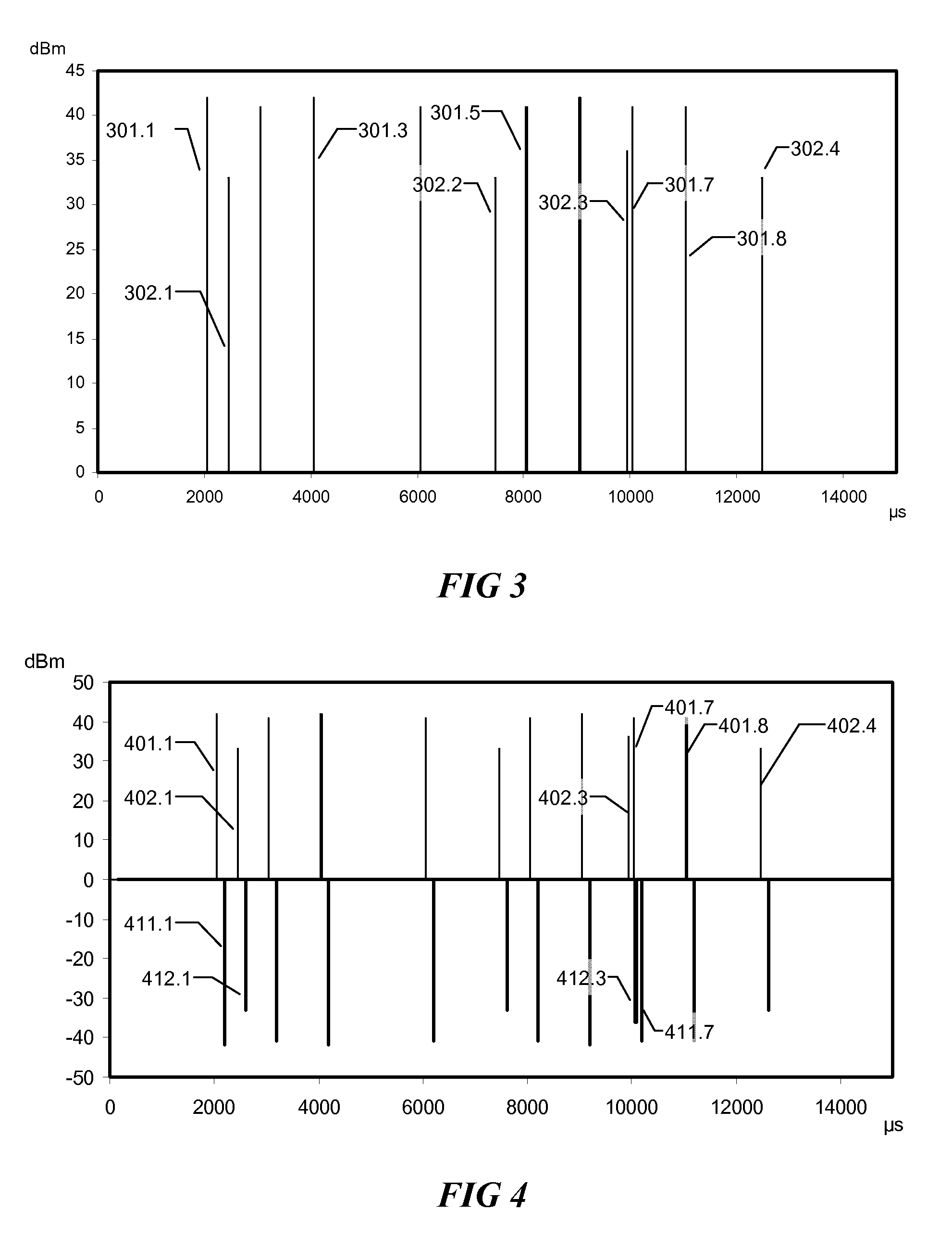
[0055]For better understanding the method, we should look first at signals reported by hardware, as those reports are the only source of data available to this method.

[0056]Radar installations transmit pulses continuously. The transmitted radar pulses are characterized (for the needs of this method) by Pulse Repetition Interval (PRI) or the reverse of it, Pulse Repetition Frequency (PRF), pulse power and pulse duration. Because the radar antenna rotates continuously and has a very good directivity, a U-NII device receives from radar installation pulses only when radar antenna is directed towards the U-NII receiver. When radar antenna is oriented in a different direction, the U-NII device does not receive enough energy from radar installation for reporting any pulse. The set of pulses received when the antenna is oriented towards the U-NII device is called a radar burst and the number of pulses in a burst depends on antenna rotation speed, antenna directivity and the PRI of the trans...


PUM


Abstract

A method for detecting radar signals consisting in identification of Presumed Pulse Repetition Intervals (PPRI) by checking the set of hardware reported signals with the time-shifted set of the same signals and checking the set of PPRI with the time-shifted images of the same set of PPRI for validating radar signals. The checking of received signals and the validation of PPRI, use functions generating scores from the difference between values of characteristics of checked elements and the standard deviation of errors from calibration measurements of the same characteristics.

Description

FIELD OF DISCLOSURE[0001]The method is applicable to wireless communication devices operating in U-NII networks in presence of radar signals and other interfering signals.UTILITY OF THE METHOD[0002]FCC and ETSI require that Unlicensed National Infrastructure (U-NII) devices operating in 5.15-5.35 GHz and 5.725-5.825 GHz have the capability of identifying signals generated by weather or military radar installations. According with current regulations, when a U-NII device detects a radar signal it should change the frequency channel for not interfering with radar operations and should not return to the same frequency for at least 30 minutes.[0003]The licensing process for devices operating in mentioned 5 GHz bands consists in passing a set of tests defined by radio frequency regulatory entities as FCC, ETSI etc. In laboratory conditions, those tests can be easily passed as no other devices operate in the same frequency band, but a reduced size network with two U-NII devices and a gene...

Claims


Application Information

Patent Timeline
IPC IPC(8): G01S7/40
CPCG01S7/023G01S7/021G01S7/0232
Inventor BELCEA, JOHN MARTIN
Owner BELCEA JOHN
Why Eureka
Try Eureka