
Wireless hearing assistance system and method

a hearing aid and wireless technology, applied in the direction of deaf-aid sets, electric devices, etc., to achieve the effect of enhancing speech intelligibility and facilitating speech for a group of speakers

Inactive Publication Date: 2012-12-13
PHONAK
View PDF5 Cites 29 Cited by
  • Summary
  • Abstract
  • Description
  • Claims
  • Application Information

AI Technical Summary

Benefits of technology

[0021]It is an object of the invention to provide for a hearing assistance system comprising a plurality of wireless microphones and at least one receiver unit, wherein the receiver unit should be adapted to be worn at ear-level and wherein audio signal transmission and processing should be relatively simple and user-friendly, so that speech intelligibility for a group of speakers, can be enhanced in an efficient manner. It is also an object to provide for a corresponding hearing assistance method.
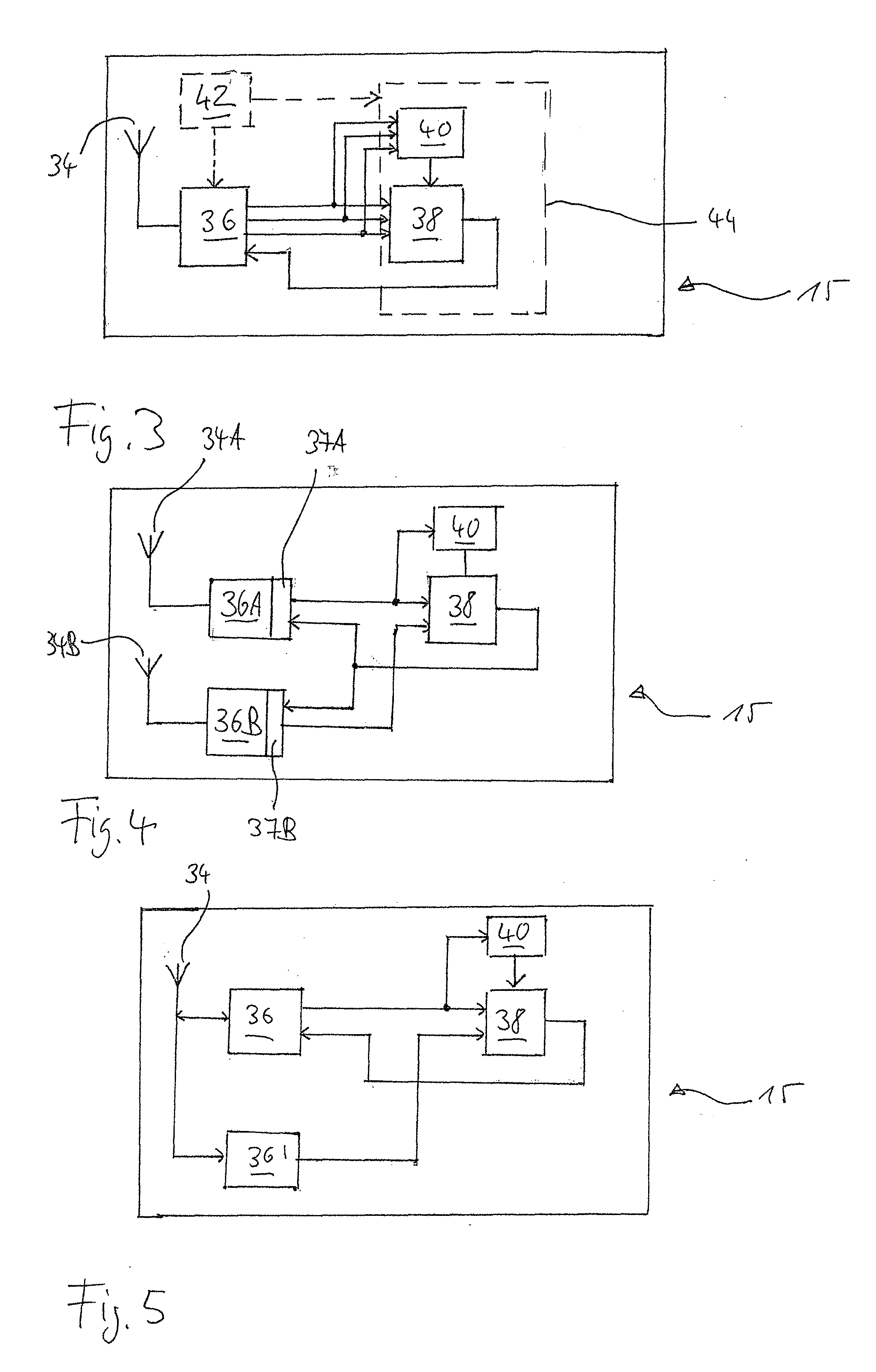
[0023]The invention is beneficial in that, by providing a relay unit for mixing the audio signals received from the transmission units and for forwarding the mixed audio signal to the receiver unit(s), ear-level design of the receiver unit is enabled, which otherwise would be prevented by the relatively high power consumption necessary for receiving several audio streams in parallel. The invention is further beneficial in that, by implementing the wireless audio link in a manner that each audio data packet is transmitted in an allocated separate slot of a TDMA frame at a different frequency selected according to a frequency-hopping sequence, a simple, user-friendly and flexible audio channel handling is achieved.

Problems solved by technology

The resulting improvements of signal level and SNR in the listener's ear are recognized as the primary benefits of FM radio systems, as hearing-impaired individuals are at a significant disadvantage when processing signals with a poor acoustical SNR.

Method used


Image

  • Wireless hearing assistance system and method
  • Wireless hearing assistance system and method
  • Wireless hearing assistance system and method

Examples


Embodiment Construction

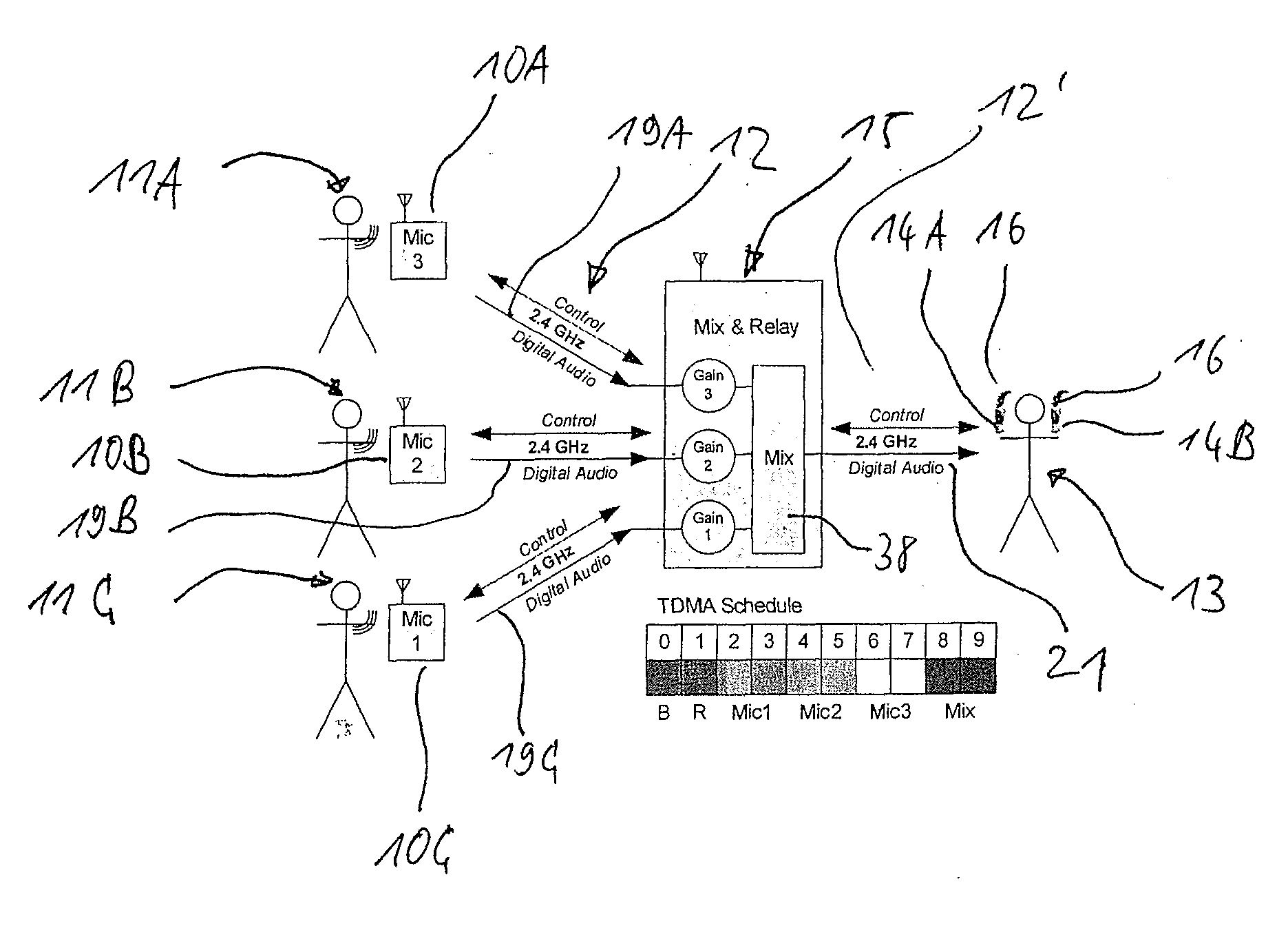
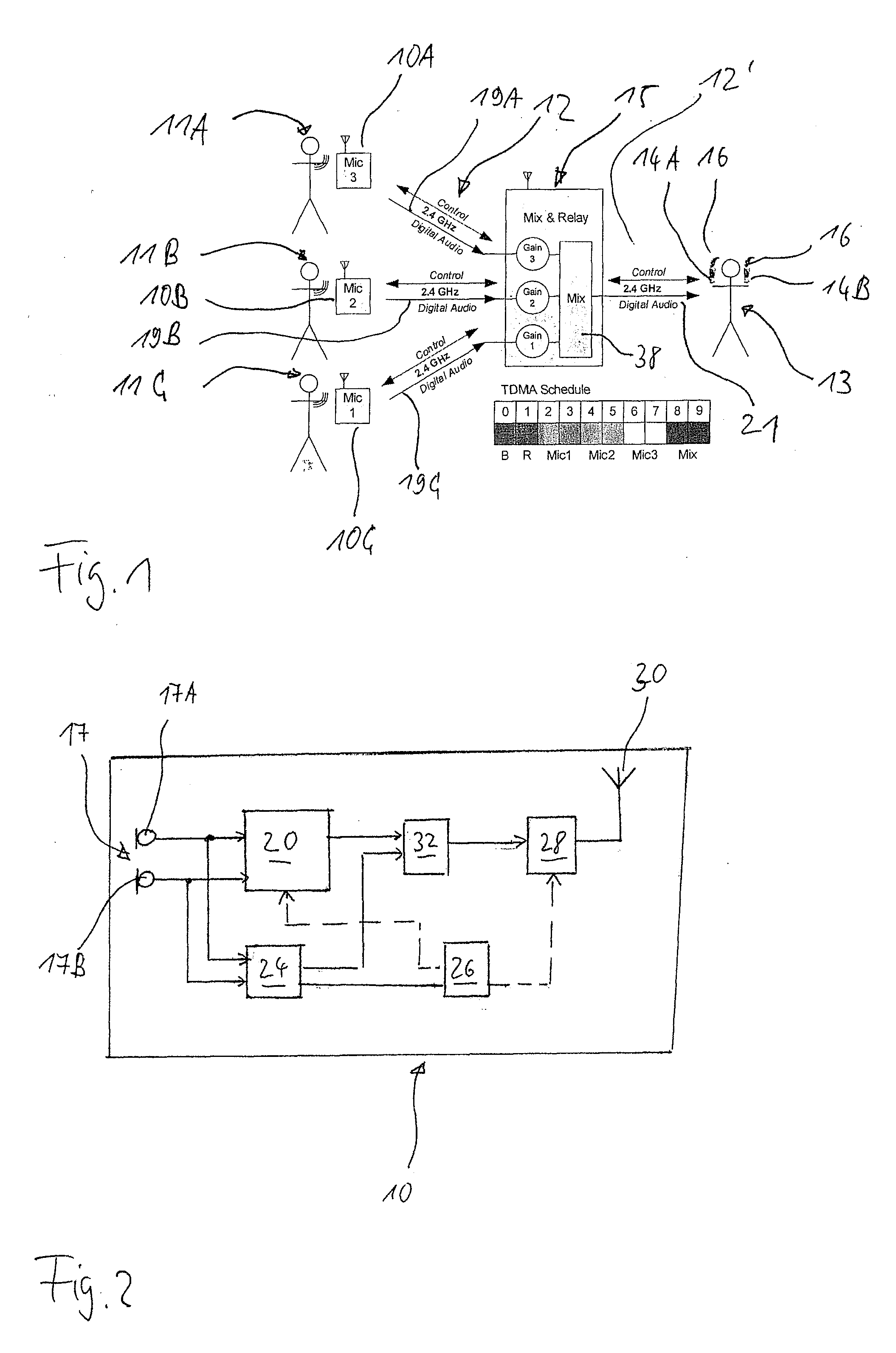
[0039]The hearing assistance system shown in FIG. 1 comprises a plurality of transmission units 10A, 10B, 10C, a relay unit 15, and two receiver units, 14A connected to a right-ear hearing aid 16 and 14B connected to a left-ear hearing aid 16 worn by a hearing impaired listener 13.

[0040]Each transmission unit 10 comprises a microphone arrangement 17 for capturing audio signals from the respective speaker's 11 voice, an audio signal processing unit 20 for processing the captured audio signals, a digital transmitter 28 and an antenna 30 for transmitting the processing audio signals as an audio stream 19 composed of audio data packets to the relay unit 15 (in FIG. 1, the audio stream from the transmission unit 10A is labeled 19A, the audio stream from the transmission unit 10B is labeled 19B, etc.). The audio streams 19A, 19B, etc. form part of a digital audio link 12 established between the transmission units 10 and the relay unit 15, which link also serves to exchange control data pa...


PUM


Abstract

A hearing assistance system having a plurality of transmission units, a microphone arrangement and a digital transmitter for transmitting audio signals as audio data packets via a wireless digital audio link; at least one user worn receiver unit; a relay unit with a mixing unit for producing a mixed audio signal from audio signals received and at least one digital transceiver for receiving audio signals from the transmission units via the digital audio link and for transmitting the mixed audio signal via the wireless digital audio link as audio data packets to a digital receiver of the receiver unit(s) for stimulating the hearing of the user(s) according to audio signals supplied from the receiver unit, the relay unit and each transmission unit transmitting each audio data packet in at least one allocated separate slot of a TDMA frame at a different frequency according to a frequency hopping sequence.

Description

BACKGROUND OF THE INVENTION[0001]1. Field of the Invention[0002]The invention relates to a system and a method for providing hearing assistance to at least one user, wherein audio signals from a plurality of wireless microphones, typically used for capturing the voice of speaker using the respective microphone, are transmitted via a wireless link to a relay unit, where the audio signals are mixed and from where a mixed audio signal is transmitted via the wireless link to a at least one receiver unit, such as an audio receiver for a hearing aid, from where the audio signals are supplied to means for stimulating the hearing of the user, such as a hearing aid loudspeaker.[0003]2. Description of Related Art[0004]Presently, in hearing assistance systems comprising a wireless microphone the wireless audio link usually is an FM (frequency modulation) radio link. According to a typical application of such wireless audio systems the receiver unit is connected to or integrated into a hearing ...

Claims


Application Information

Patent Timeline
IPC IPC(8): H04R25/00
CPCH04R25/558
Inventor EL-HOIYDI, AMRESCHMID, CHRISTOPHJOST, TIMOTHEEPLATZ, RAINERSECALL, MARC
Owner PHONAK
Learn More