Information processing apparatus, calculation method, program, and storage medium

a technology of information processing and calculation method, applied in the field of information processing apparatus, calculation method, program and storage medium, can solve the problems of unsatisfactory techniques, unsatisfactory techniques, and inability to calculate in the above-described known techniques, so as to facilitate the formation of periodical dot patterns, reduce moiré, and enhance the regularity of dot patterns

Inactive Publication Date: 2012-12-13
INT BUSINESS MASCH CORP
View PDF2 Cites 6 Cited by
  • Summary
  • Abstract
  • Description
  • Claims
  • Application Information

AI Technical Summary

Benefits of technology

[0005]A backlight unit for use in a liquid crystal display (LCD) employs a scatter dot pattern made of minute scatterers whose filling factors continuously vary on the lower surface of a light guide plate to reduce optical interference with a member including a regular pattern, such as a prism sheet or a liquid crystal cell, and to make luminance distribution uniform. In addition, to complement the advantageous effects of the dot pattern, a diffuser sheet having a scatter dot pattern disposed between the upper surface of the light guide plate and the prism sheet is also used. The scatter dot pattern has significant effect on the optical quality of the backlight from the viewpoint of the structure. To improve light utilization efficiency of a device, such as the backlight for use in the LCD, it is desirable to optimize the above scatter dot pattern.
[0006]In light of the fact that an ordered lattice produces strong moiré fringes caused by optical interference between the dot pattern and the liquid crystal cell (FIG. 14(A)), there is a known technique for reducing moiré by displacing a lattice point of the ordered lattice provided as the initial arrangement using pseudorandom numbers or by providing a dot position with pseudorandom numbers. However, if dots overlap each other, the overlapping part is visually recognized as a bright spot or a dark spot; if the distribution of the dot pattern is non-uniform, it is perceived as luminance non-uniformity (FIG. 14(B)).
[0007]Examples of a technique that aims to obtain a uniform dot pattern are described in Japanese Unexamined Patent Application Publication No. 2007-306576 (Patent Literature 1) and No. 2003-66208 (Patent Literature 2). Patent Literature 1 and Patent Literature 2 disclose a technique for making a dot pattern uniform by providing an initial arrangement of dots using a low discrepancy sequence and then solving the equation of motion in which a repulsive force is made to act between the dots. There is also a technique for optimizing the pattern by seeing a set of dots as a particle system in which a repulsive force interacts (Japanese Unexamined Patent Application Publication No. 2007-17380 (Patent Literature 3) and No. 2004-199271 (Patent Literature 4)) and solving its many-body problem. Japanese Unexamined Patent Application Publication No. 10-153779 (Patent Literature 5) discloses a technique for making a dot pattern random using random numbers such that a predetermined condition for a radial distribution function is satisfied.
[0008]The above-described issue, which aims to make distributed dots irregular and uniform, is also seen in the field of image processing. For example, Japanese Unexamined Patent Application Publication No. 2003-18404 (Patent Literature 6) and No. 2000-59626 (Patent Literature 7) disclose a technique for generating a threshold matrix using a dot pattern formed by applying a repulsive force potential in which the shape is adjusted so as to facilitate formation of a periodical dot pattern in a local region to each dot with the aim of enhancing regularity of the dot pattern in the local region and improving the uniformity and virtual image issue. In relation to other dot patterns, a dot pattern smoothing method for performing complementary processing on dots above, below, to the left, and to the right of a dot to be processed according to the rule is disclosed in Japanese Unexamined Patent Application Publication No. 8-227456 (Patent Literature 8), and a process for calculating the length of a space between dots is disclosed in Japanese Unexamined Patent Application Publication No. 2006-310988 (Patent Literature 9). As a method for optimizing an image pattern, a dithering optimization technique for generating an improved matrix by swapping values in a dither matrix, forming an objective function, and optimizing that objective function with the aim of providing an improved dithering optimization method for displaying an image on a discrete level output display by the use of a process for efficiently assigning an intensity value element in the dither matrix is disclosed in Japanese Unexamined Patent Application Publication No. 6-318249 (Patent Literature 10).
[0009]The techniques disclosed in Patent Literature 1 and Patent Literature 2 correspond to solving a potential by the steepest-decent method and can provide a dot pattern that has a good quality to some extent. However, for the known techniques of Patent Literature 1 and Patent Literature 2, it is necessary to calculate a repulsive force that acts between many points in solving the equation of motion as a multi-body problem, and computational complexity surges on the order of the square of the input size at worst. In recent years, because the number of dots required in the above scatter pattern has increased with the increase in the size of a liquid crystal display, the calculation time in the above-described known techniques is undesirably long, and these techniques are unsatisfactory from the viewpoint of supporting the increase in the device size.BRIEF SUMMARY OF THE INVENTION
[0010]In order to overcome these deficiencies, the present invention provides an information processing apparatus for calculating a spatial arrangement of a plurality of elements of a discrete pattern, the plurality of elements being arranged in a spatially discrete manner, the information processing apparatus including: a placing unit configured to determine, for each of the elements, a density in an initial position given to the element from a density distribution of the elements in a region where the elements are arranged in the discrete pattern and configured to place, for each of the elements, a figure and a movement range of the figure, the figure having a size corresponding to the density and representing a region where the element repels other elements; a computation unit configured to minimize an objective function for imposing a penalty on each of a collision between the figures and a protrusion of the figure from the movement range using a position of each of the figures as a decision variable and configured to compute an optimal solution of the position of each of the figures; and an output unit configured to output the optimal solutions of the positions of the figures as the spatial arrangement of the elements.

Problems solved by technology

However, for the known techniques of Patent Literature 1 and Patent Literature 2, it is necessary to calculate a repulsive force that acts between many points in solving the equation of motion as a multi-body problem, and computational complexity surges on the order of the square of the input size at worst.
In recent years, because the number of dots required in the above scatter pattern has increased with the increase in the size of a liquid crystal display, the calculation time in the above-described known techniques is undesirably long, and these techniques are unsatisfactory from the viewpoint of supporting the increase in the device size.

Method used


Image

  • Information processing apparatus, calculation method, program, and storage medium
  • Information processing apparatus, calculation method, program, and storage medium
  • Information processing apparatus, calculation method, program, and storage medium

Examples


experimental examples

2. Experimental Examples

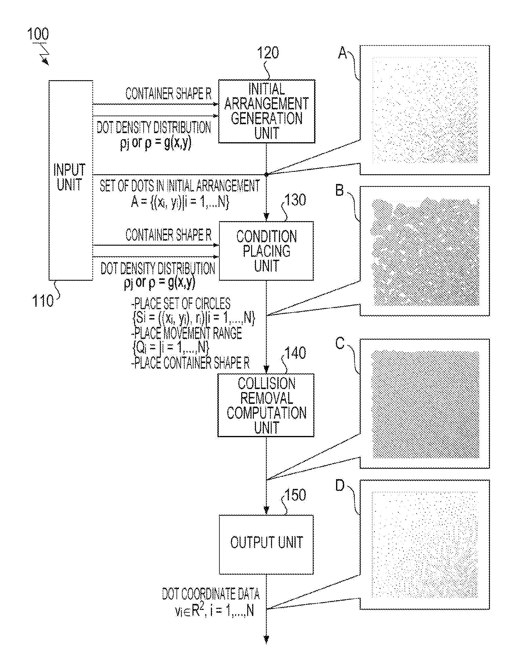
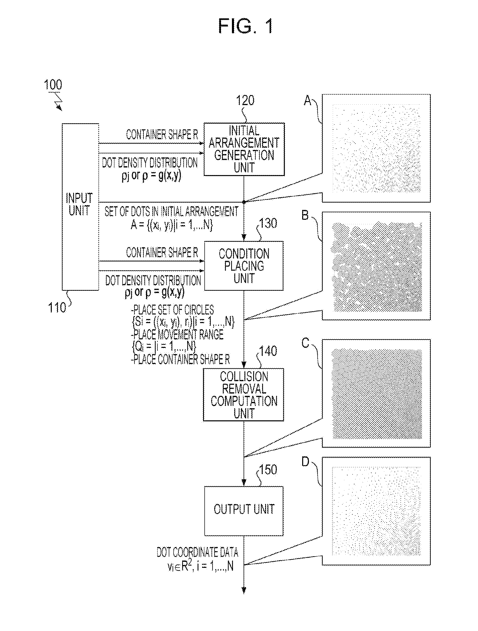
[0079]A design condition is that the movement range Qi was a square having a side of 4ri where ri is the radius of a circle, the constant a in the above Expression (7) for determining the radius ri is π / √3, and the dot diameter 2ro is 46 μm.

2.1. Experimental Example 1 (Implementation)

[0080]A design condition is that, in addition, the container R is a square region having a side of 3.0 cm. The used filling factor distribution data is one in which the filling factor in the central portion is 60%, the filling factor in the outer portion is 0%, and a mean gradient is 40% / cm. When processing of generating a scatter dot pattern for an LED light in which 110,000 dots in total are arranged was performed using the dot-pattern generating apparatus according to the implementation of the present invention, it converged on an equilibrium state in 108 seconds from the start of the computation.

2.2. Experimental Example 2 (Implementation)

[0081]When the container R is a recta...


PUM


Abstract

An information processing apparatus, a calculation method, a program, and a storage medium for generating a uniformly distributed discrete pattern. To calculate a spatial arrangement of a plurality of elements of a discrete pattern, the plurality of elements being arranged in a spatially discrete manner, an information processing apparatus according to the present invention determines, for each of the elements, a density in an initial position given to the element from a density distribution of the elements in a region where the elements are arranged in the discrete pattern and places, for the initial position of each of the elements, a figure having a size corresponding to the density and representing a region where the element repels other elements and a movement range of the figure. The information processing apparatus minimizes an objective function, computes an optimal solution, and outputs the optimal solutions.

Description

CROSS REFERENCE TO RELATED APPLICATION[0001]This application is a continuation of and claims priority from U.S. application Ser. No. 13 / 441,981 filed on Apr. 9, 2012, which in turn claims priority under 35 U.S.C. 119 from Japanese Application 2011-088093, filed Apr. 12, 2011, the entire contents of both applications are incorporated herein by reference.BACKGROUND OF THE INVENTION[0002]1. Field of the Invention[0003]The present invention relates to processing for generating a discrete pattern, and more specifically, to an information processing apparatus, a calculation method, a program, and a storage medium for generating a uniformly distributed discrete pattern.[0004]2. Description of the Related Art[0005]A backlight unit for use in a liquid crystal display (LCD) employs a scatter dot pattern made of minute scatterers whose filling factors continuously vary on the lower surface of a light guide plate to reduce optical interference with a member including a regular pattern, such as ...

Claims


Application Information

Patent Timeline
Patent Type & Authority Applications(United States)
IPC IPC(8): G06K9/36
CPCG02B6/0043G02B6/0061G06T11/00G02F1/133606G02B6/0065G02B6/004
Inventor IDE, TSUYOSHIIMAMICHI, TAKASHINUMATA, HIDETOSHI
Owner INT BUSINESS MASCH CORP
Why Eureka
Try Eureka