Film forming apparatus, film forming method, method for optimizing rotational speed, and storage medium

a film forming and film forming technology, applied in the direction of liquid surface applicators, coatings, chemical vapor deposition coatings, etc., can solve the problems of non-uniform film thickness in the substrate, non-uniform film on the substrate, and more serious problems, so as to prevent the lowering of the in-plane uniform thickness of the film formed, the effect of eliminating the dependency on gas supply direction

Active Publication Date: 2012-12-13
TOKYO ELECTRON LTD
View PDF2 Cites 73 Cited by
  • Summary
  • Abstract
  • Description
  • Claims
  • Application Information

AI Technical Summary

Benefits of technology

[0056]The film forming apparatus, the film forming method, the method for optimizing a rotational speed and the storage medium of the present invention can achieve the following advantageous effects:
[0057]In a process for forming a film on an object to be processed by sequentially supplying a gas (gases) to the surface of the object to be processed and thereby laminating layers of a reaction product, the rotational speed of the objec

Problems solved by technology

Also in an ALD process, the adhesion probability affects the adsorption rate of a raw material vapor and the rate of a reaction between adsorbed raw materials and, when the time for supply of a reactive gas is short, can cause the problem of non-uniform film thickness in a substrate due to the influence of gas supply direction.
In addition, the recent movement toward larger substrates makes the problem more serious because a gas supply nozzle must deal with a large substrate processing area.
Therefore, when a substrate is rotated, it is possible that the gas may be s

Method used


Image

  • Film forming apparatus, film forming method, method for optimizing rotational speed, and storage medium
  • Film forming apparatus, film forming method, method for optimizing rotational speed, and storage medium
  • Film forming apparatus, film forming method, method for optimizing rotational speed, and storage medium

Examples


first embodiment

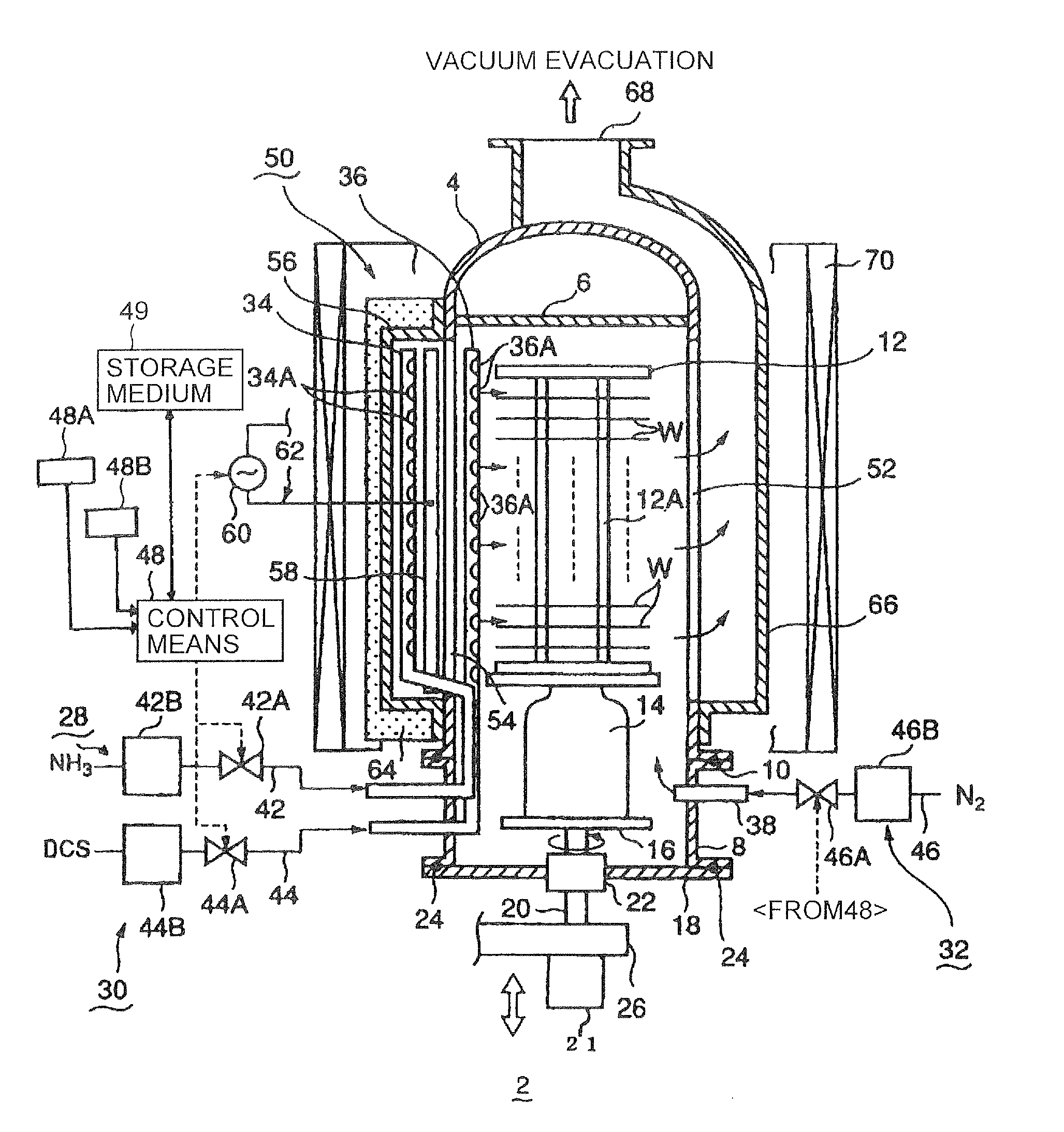
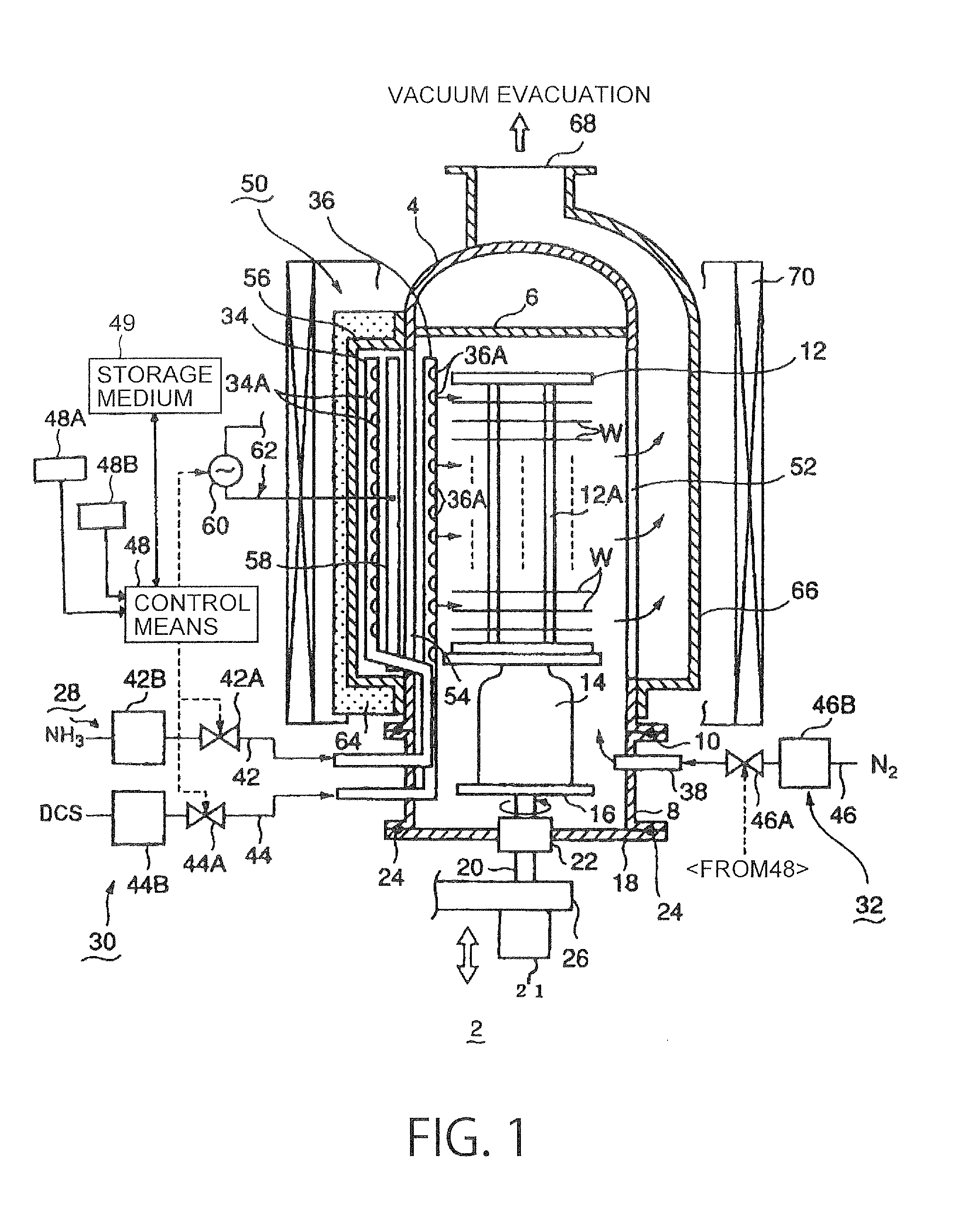
[0118]An ALD film forming process comprising 30 ALD cycles, carried out under the above-described conditions 2 using the film forming apparatus 2 of the present invention, will now be described. First, operating conditions for the apparatus are inputted into the control means 48 in advance. In particular, a processing recipe containing data on the conditions 2 and the division number K which determines the number of processing gas supply starting directions, in addition to data on the processing temperature, the processing pressure, the gas flow rate, etc., is inputted by an operator from the processing condition input means 48A connected to the control means 48. Alternatively, such a processing recipe may be sent to the control means 48 from a host computer. The control means 48 determines a rotational speed which satisfies the division number K specified by a stored program. Assuming that “30” is specified as the division number K by the processing recipe, the substrate rotational...

second embodiment

[0138]An ALD film forming process comprising 30 ALD cycles, carried out at a fixed rotational speed while controlling an ALD cycle time T under the above-described conditions 2, using the film forming apparatus 2 of the present invention, will now be described.

[0139]First, as with the first embodiment, operating conditions for the apparatus are inputted into the control means 48 in advance. The control means 48 can change an ALD cycle time T, e.g. by adjusting the time for evacuating and purging the processing container, without changing the order of supply of reactive gases, the time for supply of each gas and the amount of each gas supplied, which are specified in the operating conditions. When K=30 and the substrate rotational speed N1=1.9 (rpm), the period T1 of one ALD cycle is determined by the control means 48 through the following calculation. Processing gases can be supplied at predetermined appropriate timings, whereby the advantageous effects of the present invention can ...

third embodiment

[0182]Using the above-described relation, an ALD cycle time Tx can be determined in the case where K=160, the resolution Q of the motor used is 200 and the rotational speed N is rounded to the whole number in the timing graph of conditions 2, as follows:

R=K / Q=160 / 200=4 / 5

[0183]The following expression can be derived from the above expression (9): 4·α=5·β

[0184]When the step angle β=1.8°, 5·β=5×1.8°=9°.

[0185]When 4·α is taken as a new shift angle, 4×2.25°=9°.

[0186]Therefore, a new division number is 360 / 9=40.

[0187]The following relational expression can be derived from the above expression (3): (n±1 / 40)=(1 / 60)×2×Tx

[0188]Table 1 below shows the values of n and Tx which satisfy this relational expression.

TABLE 1n1234Tx(+)30.7560.7590.75120.75(−)29.2559.2589.25119.25

[0189]The Tx value of 90.75 in the case of n=3, + can be used by shortening the ALD cycle time from 95 seconds to 90.75 seconds.

[0190]It is also possible to use the Tx value of 119.25 in the case of n=4, − and change the ALD c...


PUM

PropertyMeasurementUnit
Lengthaaaaaaaaaa
Timeaaaaaaaaaa
Timeaaaaaaaaaa

Abstract

A film forming apparatus for forming a film on an object includes: a processing container; gas supply means, having gas jet ports, respectively; a holding means for holding the object; a drive mechanism for moving the holding means relative to the gas jet ports; and a control means which, when repeating P times a cycle, consisting of a supply period for supplying a gas and a supply stop period during which the supply of the gas is stopped, performs control so that as viewed from the center of the object, a gas supply starting position is sequentially shifted in the circumferential direction of the object for every cycle in such a manner that the entire circumference of the object to be processed is divided into K segments (K=P), K being an arbitrary division number, and the gas supply starting position is shifted by one segment for every cycle.

Description

TECHNICAL FIELD[0001]The present invention relates to a film forming apparatus, a film forming method, a method for optimizing a rotational speed and a storage medium which are for forming a multi-layer film of a reaction product by repeating the cycle of supplying at least one reactive gas to a surface of a substrate, such as a semiconductor wafer.BACKGROUND ART[0002]As a film forming method for use in a semiconductor manufacturing process, a film forming process is known which involves a repetition of a processing cycle of supplying a first reactive gas to a surface of a semiconductor wafer (hereinafter also referred to simply as “wafer”) as a substrate in a vacuum atmosphere to adsorb the gas onto the wafer surface, and then switching the gas to a second reactive gas to form an atomic or molecular layer or layers by a reaction between the first and second gases. By repeating the cycle a number of times, a multi-layer film of the reaction product can be formed on the substrate. Su...

Claims


Application Information

Patent Timeline
IPC IPC(8): C23C16/52
CPCC23C16/345C23C16/45578C23C16/4584C23C16/45546C23C16/515C23C16/45525C23C16/507C23C16/52C23C16/455H01L21/205H01L21/31
Inventor ITO, SHOZO
Owner TOKYO ELECTRON LTD
Why Eureka
Try Eureka