Two part eeg monitor with databus and method of communicating between the parts

Active Publication Date: 2012-12-13
T&W ENG
View PDF9 Cites 16 Cited by
  • Summary
  • Abstract
  • Description
  • Claims
  • Application Information

AI Technical Summary

Benefits of technology

[0028]In an embodiment of the EEG monitor where a receiver is arranged in the electrode part, the receiver is connected such that it will not draw any power in the time where data is transferred on the databus, but only in the time where power is transferred. This can be achieved by short-circuiting the receiver during the transfer of data. The advantage of this will be that the receiver will not need to draw power from a capacitor in the electrode part during the time w

Problems solved by technology

Hypoglycaemic attacks may lead to unconsciousness and even death.
One problem in having such a transducer, e.g. a microphone, is that the wires used for transferring the signal from the transducer to the base part may pick up electromagnetic interference.
This problem is larger when a receiver is arranged in the electrode part, since the wires supplying the receiver signal, which may be 2 V at peak level, will be arranged close to the wires transferring the signal from the EEG electrodes and e.g. from a transducer.
Therefore, there may b

Method used


Image

  • Two part eeg monitor with databus and method of communicating between the parts
  • Two part eeg monitor with databus and method of communicating between the parts
  • Two part eeg monitor with databus and method of communicating between the parts

Examples


Embodiment Construction

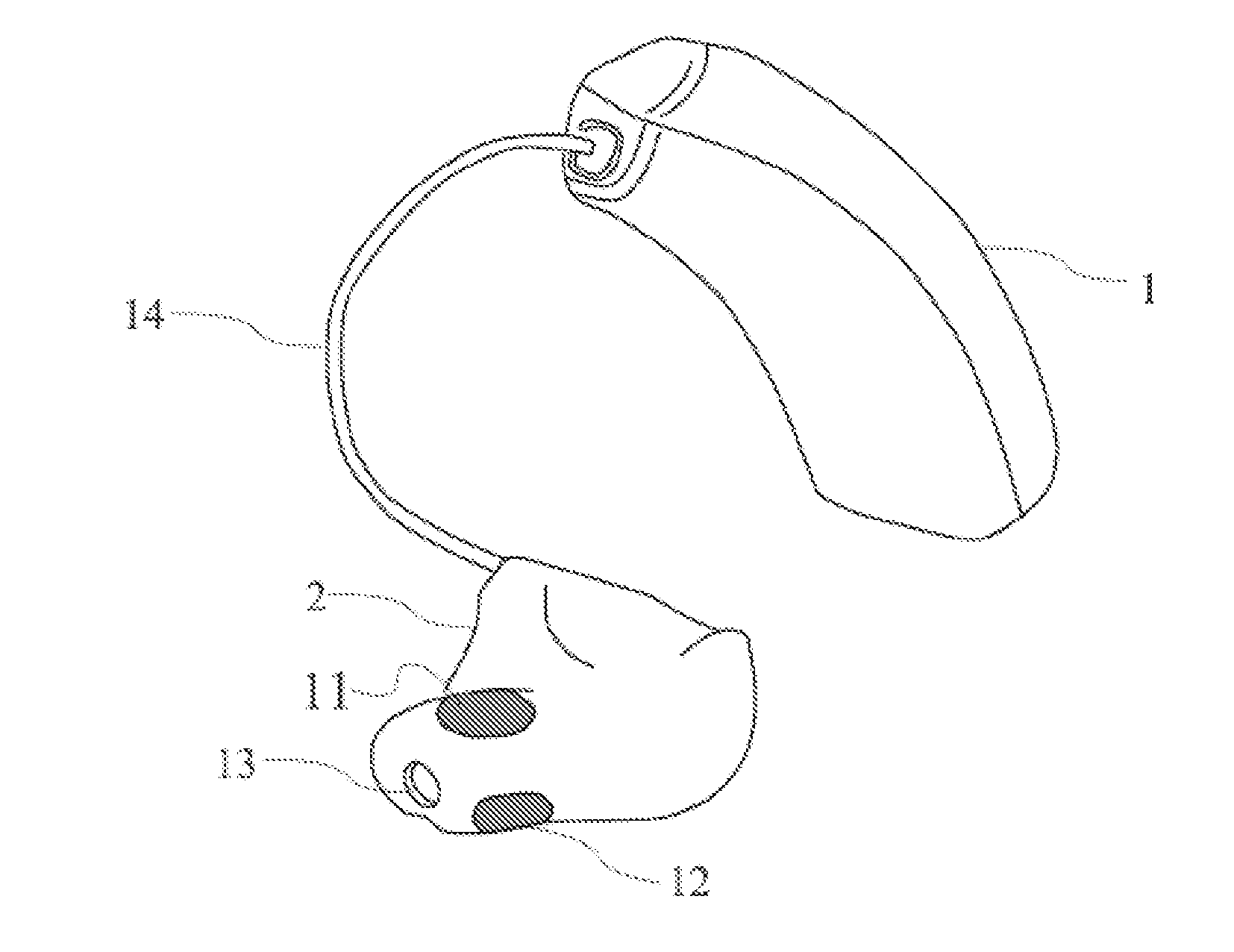
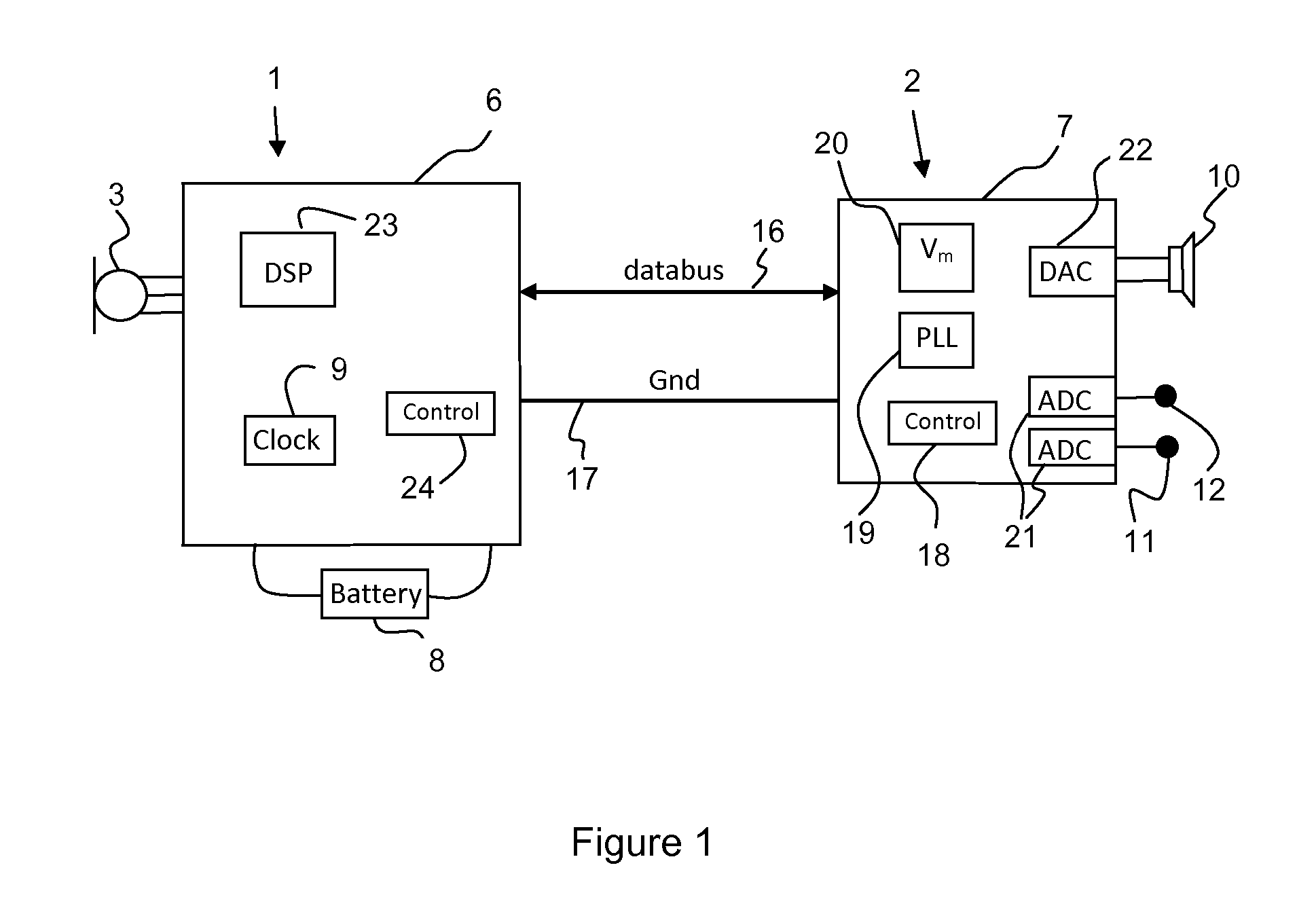
[0042]FIG. 1 shows the principles of an EEG monitor where the base part 1, often arranged behind the ear, comprises an electronic module 6, and a battery 8. The electronic module 6 comprises signal processing means 23, a clock generator 9 and a controller 24 for controlling the communication on the data line or databus 16. The base part may also comprise a microphone 3, which can be applied for building a hearing aid capability into the EEG monitor or for adjusting the sound pressure level of any sounds from the receiver 10 in the electrode part 2 to the background acoustical noise level. Both for FIG. 1 and the following Figs. the description is focused on embodiments where a bidirectional databus is applied, and where a receiver or speaker is arranged in the electrode part.

[0043]The electrode part 2 of the EEG monitor comprises an electronic module 7 (i.e. an electronic chip or an integrated circuit) and two or more EEG electrodes 11, 12 for measuring the EEG signal of a person to...


PUM


Abstract

A personal wearable EEG monitor comprises a base part (1) having signal processing means (23), and an electrode part (2) with at least two electrodes (11, 12) for measuring an EEG signal of a person. The electrode part (2) comprises means for converting the EEG signal into a digital signal. The EEG monitor comprises a databus for transferring data between the base part (1) and the electrode part (2) and for providing power from one part to the other. The databus is adapted for application of two electrical wires. The invention further provides a method for communicating between two parts of an EEG monitor.

Description

RELATED APPLICATIONS[0001]The present application is a continuation-in-part of application PCT / EP2011053518, filed on Mar. 9, 2011, in Europe and published as WO 2011 / 110582 A1. The present application is a continuation-in-part of application PCT / EP2010 / 052960, filed on Mar. 9, 2010, in Europe and published as WO 2011 / 110218 A1.BACKGROUND OF THE INVENTION[0002]1. Field of the Invention[0003]The present invention relates to EEG monitors. The invention further relates to an EEG monitor in two parts connected with electrical wires. The invention more specifically concerns an EEG monitor comprising power supply means. The invention further relates to a method for communicating between two parts of an EEG monitor.[0004]EEG is the commonly used abbreviation for Electro Encephalo-Gram, which is generally speaking a method of electrically monitoring brain activity of a person. Systems for monitoring EEGs have been known for many years. However with the general technological development, EEG...

Claims


Application Information

Patent Timeline
IPC IPC(8): A61B5/0478A61B5/0482A61B5/0476A61B5/296A61B5/375
CPCA61B5/0476A61B5/6817A61B2560/0214A61B2560/0219H04R2460/03H02J7/345H04R25/60H04R2225/021G06F1/266H04B3/542H04R2225/57H04R25/609H04R2225/0216A61B5/369H02J2310/23A61B5/291A61B5/7253A61B5/256A61B5/6803A61B5/6815
Inventor KILSGAARD, SORENKIDMOSE, PREBENRANK, MIKE LIND
Owner T&W ENG
Why Eureka
Try Eureka