
Pulse simulation unit

a simulation unit and pulse technology, applied in educational appliances, instruments, educational models, etc., can solve the problems of short time margins, high labor intensity, and severe pain and/or losses of patients and their relatives,

Inactive Publication Date: 2013-07-11
LAERDAL MEDICAL AS
View PDF0 Cites 2 Cited by
  • Summary
  • Abstract
  • Description
  • Claims
  • Application Information

AI Technical Summary

Benefits of technology

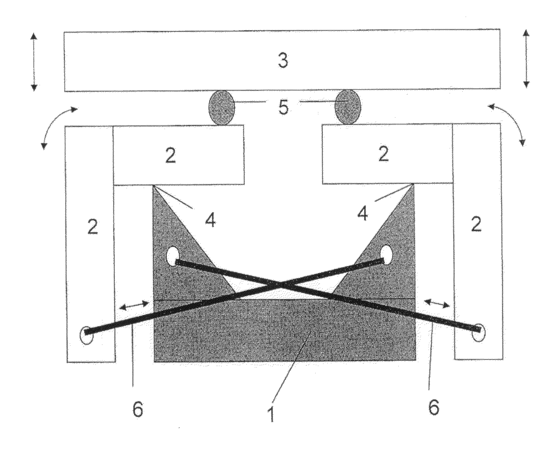
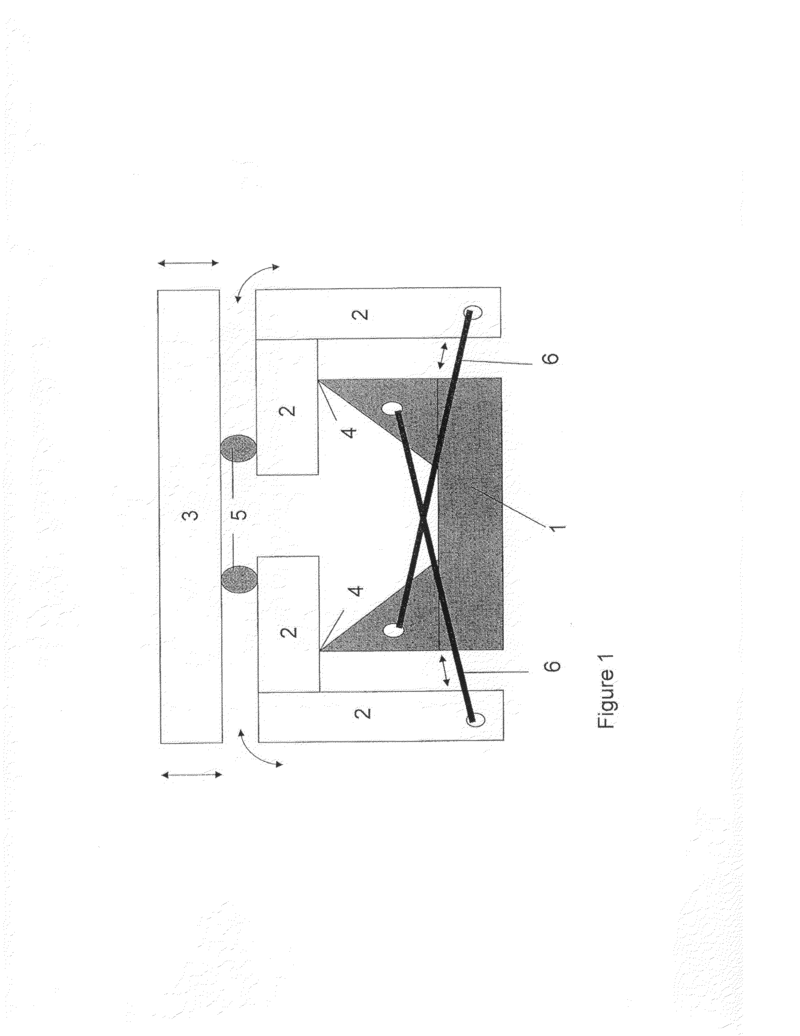
The invention describes a device that can mimic a pulse beat by using a wire made of shape memory alloy. This alloy can contract when exposed to an electrical current and expand back to its original length when the current is removed. The device is controlled by adjusting the potential difference and duration of the electrical pulses delivered to the wire. A mechanical structure is used to transform the contraction movement of the wire into an expansion force, and the device is placed under the artificial skin of a patient simulator manikin. This device can help to simulate normal or abnormal cardiac rhythms. The device is simple and cost-effective, and can be used in infants or babies. The control signals can directly come from the manikin's CPU.

Problems solved by technology

There are serious ethical aspects involved in making errors causing severe pain and / or losses for the patients and their relatives.
The workplace environment in such places is often technologically complex and there may be short time margins between occurrence of an incident and the required correct response to avoid severe consequences.
There are also typically considerable risks involved in misjudgements, placing a high stress on the operator(s) taking care of the incident.

Method used


Image

  • Pulse simulation unit
  • Pulse simulation unit
  • Pulse simulation unit

Examples


example embodiment

OF THE INVENTION

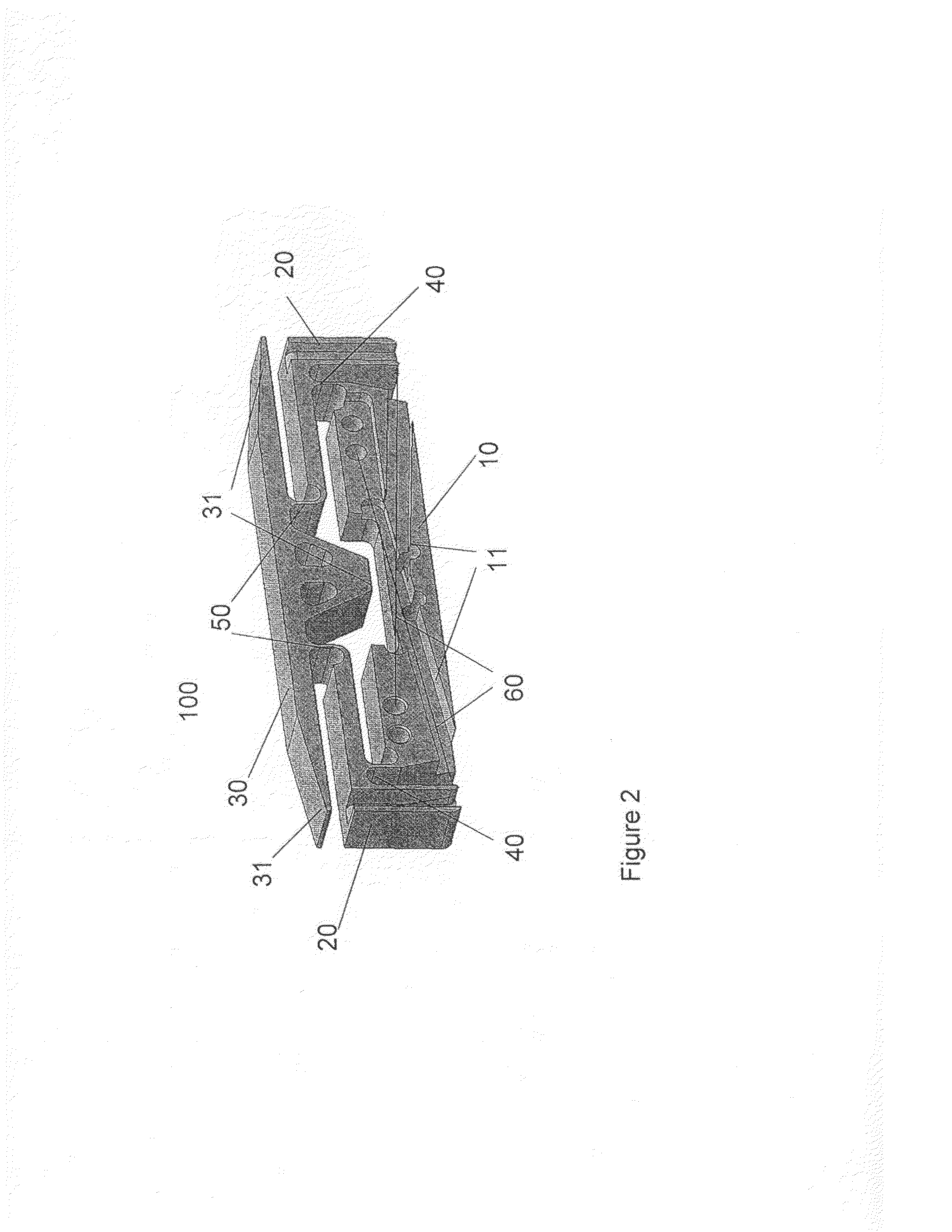
[0022]The invention will be described in further detail by way of an example embodiment shown from the side and somewhat from above in FIG. 2.

[0023]The example embodiment 100 is made of two parts, a plastic structure and two shape memory alloy actuator wires 60. The plastic structure has an overall shape of a rectangular parallelepiped with dimensions 30×5×8 mm3, and is composed of one piece consisting of a base body 10 pivotally connected to two lever bodies 20 by narrow bridging sections 40, and each lever body is pivotally connected to an actuator body 30 by narrow bridging sections 50. That is the base body, lever bodies and actuator body is made out of one piece of plastic to form a continuous interconnected structure which is able to transform the contraction of the actuator wires into an expansion movement of the actuator body. The plastic structure may be formed by compression moulding, injection moulding etc., and is made of polyoxymethylene.

[0024]The narrow...


PUM


Abstract

This invention relates to pulse simulation units for use in patient simulators, where the device comprises a base body, an upper actuator body located in parallel above the base body, one leaver body at each longitudinal end of the base body, which in their lower portion is pivotally attached to the base body and in their upper portion is pivotally attached to the actuator body, and at least one shape memory alloy wire attached in one end to the lower portion of each leaver body below the pivotally attachment to the base body and in the other end to the base body, and where the length of the shape memory alloy actuator wire is adjusted such that when no electric pulse is delivered, the length of the wire(s) allow the leaver bodies to be more or less folded in towards the base body and hold the actuator body to form a compressed position at a first distance above the base body, and such that when the actuator wire(s) contract due to exposure to an electric pulse they will rotate the lever bodies some degrees and thus cause the actuator body to be lifted to an expanded position at a second distance>the first distance above the base body.

Description

BACKGROUND[0001]According to Asgaut Viste at Department of Surgical Studies at the University in Bergen, medical mistreatment causes more deaths than deaths from AIDS, traffic accidents, and breast cancer [1]. There are serious ethical aspects involved in making errors causing severe pain and / or losses for the patients and their relatives. Another aspect is that there are huge economical and capacity savings at hospitals / -medical institutions involved by preventing medical mistreatment from happening, as compared to costs associated with treating / alleviating the damage caused by erroneous medical treatment.[0002]Training personnel to handle emergency situations have long been mandatory in safety critical applications such as aviation, shipping, process industry etc. by use of simulating potential accidents / incidents. The workplace environment in such places is often technologically complex and there may be short time margins between occurrence of an incident and the required correct...

Claims


Application Information

Patent Timeline
Patent Type & Authority Applications(United States)
IPC IPC(8): G09B23/28
CPCG09B23/288G09B23/28
Inventor HETLAND, EIRIK
Owner LAERDAL MEDICAL AS
Learn More