Heat pump system for vehicle

a heat pump and vehicle technology, applied in the field of heat pump systems, can solve the problems of excessive electric power consumption of electric heaters, deterioration of heat exchange efficiency of heat exchange media, and excessive travel distance of electric vehicles, so as to improve heating performance and dehumidification efficiency

Inactive Publication Date: 2012-12-20
HYUNDAI MOTOR CO LTD +1
View PDF4 Cites 26 Cited by
  • Summary
  • Abstract
  • Description
  • Claims
  • Application Information

AI Technical Summary

Benefits of technology

[0019]Various aspects of the present invention are directed to providing a heat pump system for a vehicle having advantages of using a waste heat source in electric devices to heat coolant and exchanging the heat between the coolant and refrigerant to improve heating performance and dehumidification efficiency, and to prevent frost accumulation on the outside condenser in a low temperature, and a control method thereof.

Problems solved by technology

But, the electric heater excessively consumes electric power to reduce a travel distance of the electric vehicle.
Also, the refrigerant that is cooled by outside air of a very low temperature or a low temperature in winter is cooled by an interior condenser to be exhausted in a very low temperature condition to an outside condenser, and therefore ice is formed on a surface of the outside condenser and heat exchange efficiency of the heat exchange media and heating performance and efficiency are deteriorated, and in a case that the cooling mode is transformed to the heating mode, the condensate that stays on the evaporator increases humidity such that moisture is formed on the interior of the glass of the vehicle.
Therefore, heating performance may be seriously deteriorated, the heating load may be increased due to the increase of power consumption, and the mileage may be decreased when driving while warming.
In addition, since heat for converting the liquid refrigerant into a gaseous refrigerant is insufficient when the liquid refrigerant flows into the interior condenser, compressing efficiency may be deteriorated, heating performance may be seriously deteriorated when the air temperature is low, the system may be unstable, and durability of the compressor may be deteriorated when the liquid refrigerant flows into the compressor
In addition, noise and vibration may occur due to a frequent open / close operation of a 2-way valve in a dehumidification mode where moisture is removed from the cabin of the vehicle.

Method used


Image

  • Heat pump system for vehicle
  • Heat pump system for vehicle
  • Heat pump system for vehicle

Examples


Embodiment Construction

[0042]Reference will now be made in detail to various embodiments of the present invention(s), examples of which are illustrated in the accompanying drawings and described below. While the invention(s) will be described in conjunction with exemplary embodiments, it will be understood that the present description is not intended to limit the invention(s) to those exemplary embodiments. On the contrary, the invention(s) is / are intended to cover not only the exemplary embodiments, but also various alternatives, modifications, equivalents and other embodiments, which may be included within the spirit and scope of the invention as defined by the appended claims.

[0043]An exemplary embodiment of the present invention will hereinafter be described in detail with reference to the accompanying drawings.

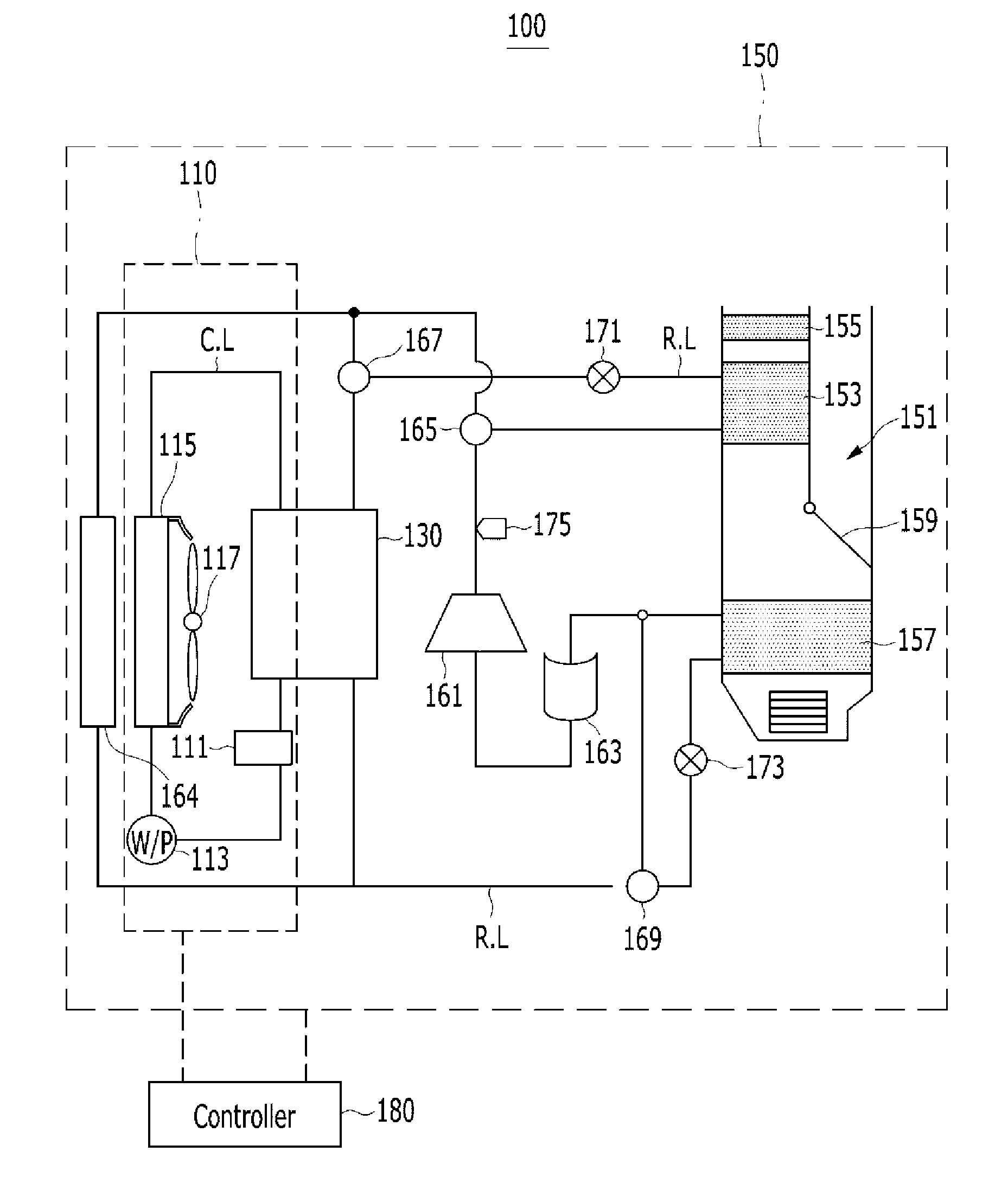
[0044]FIG. 1 is a block diagram of a heat pump system for a vehicle according to an exemplary embodiment of the present invention.

[0045]Referring to the drawings, the heat pump system 100 for a...


PUM


Abstract

A heat pump system may include a cooling assembly disposed on a vehicle to circulate electric devices with coolant through a cooling line, wherein the cooling assembly includes a radiator disposed at a front side of the vehicle, uses a water pump to circulate coolant through the cooling line, and cools the supplied coolant through heat exchange with outside air, and a cooling fan that blows wind through the radiator, an air conditioning assembly connected to a refrigerant line connected to the cooling assembly to control heating and cooling, and a heat exchanger connected to the cooling line such that the coolant is circulated therein, selectively uses the waste heat generated from the electric devices according to modes to vary the temperature of the coolant, and is connected to the refrigerant line of the air conditioning assembly such that an inflow refrigerant exchanges heat with the coolant.

Description

CROSS-REFERENCE TO RELATED APPLICATION[0001]The present application claims priority to Korean Patent Application No. 10-2011-0059768 filed in the Korean Intellectual Property Office on Jun. 20, 2011, the entire contents of which is incorporated herein for all purposes by this reference.BACKGROUND OF THE INVENTION[0002]1. Field of the Invention[0003]The present invention relates to a heat pump system and a control method thereof. More particularly, the present invention relates to a heat pump system that uses waste heat that is generated from electric devices, improves heating and dehumidifying performance, prevents front accumulation on an outside condenser at a low temperature, and simultaneously increases a travel distance, and a control method thereof.[0004]2. Description of Related Art[0005]Generally, an air conditioning system for a vehicle includes an air conditioning module warming or cooling a cabin of the vehicle.[0006]Such an air conditioning module circulates a heat-excha...

Claims


Application Information

Patent Timeline
Patent Type & Authority Applications(United States)
IPC IPC(8): F25B29/00F25B49/02F28D15/00
CPCB60H1/00921B60H2001/00949B60H1/143B60H1/3228B60H1/00899B60H1/00792B60H1/00385
Inventor CHOI, YONG HYUNKIM, JAE YEONCHA, YONG WOONGCHO, WAN JEPARK, JUNGHAKIM, JAESANPARK, MAN HEE
Owner HYUNDAI MOTOR CO LTD
Why Eureka
Try Eureka