Elevator system

Active Publication Date: 2012-12-20
KONE CORP
View PDF14 Cites 17 Cited by
  • Summary
  • Abstract
  • Description
  • Claims
  • Application Information

AI Technical Summary

Benefits of technology

[0020]As a result of the invention an elevator system can easily be adapted to changing conditions and traffic needs by disposing portable call terminals on different floor levels according to need. At the same time the optimal operation and transport capacity of the elevator system can be ensured by taking into account in the control of the elevator system the actual location of the call terminals. Congestion of elevator lobbies can also be reduced by placing call terminals in locations that are critical from the viewpoint of traffic and by guiding passenger flows in good time (remotely) to uncongested elevator lobbies. If the desired result is not achieved immediately, the call terminals can easily be moved to a new location for finding the optimal placement in the building. Passengers also receive accurate guidance no matter in which location in the building a call terminal is, as a consequence of which passengers quickly and easily find their way to the elevator/elevator group serving them. No special servicing visits are needed for setting the position data and the values of the other parameters, but instead the necessary procedures can be performed e.g. by a person who works in the building on a daily basis. If a p

Problems solved by technology

A problem with call terminals that are fixed installations is, inter alia, that they adapt poorly to changes occurring in a building, e.g. if the intended use of the building changes or if large numbers of people sporadically visit the building.
Call terminals could also have been installed originally in unsuitable locations from the viewpoint of the smooth flow of traffic, in which case the elevator lobbies can become needlessly congested.
The addition of fixed call terminals or

Method used


Image

  • Elevator system
  • Elevator system

Examples


Example

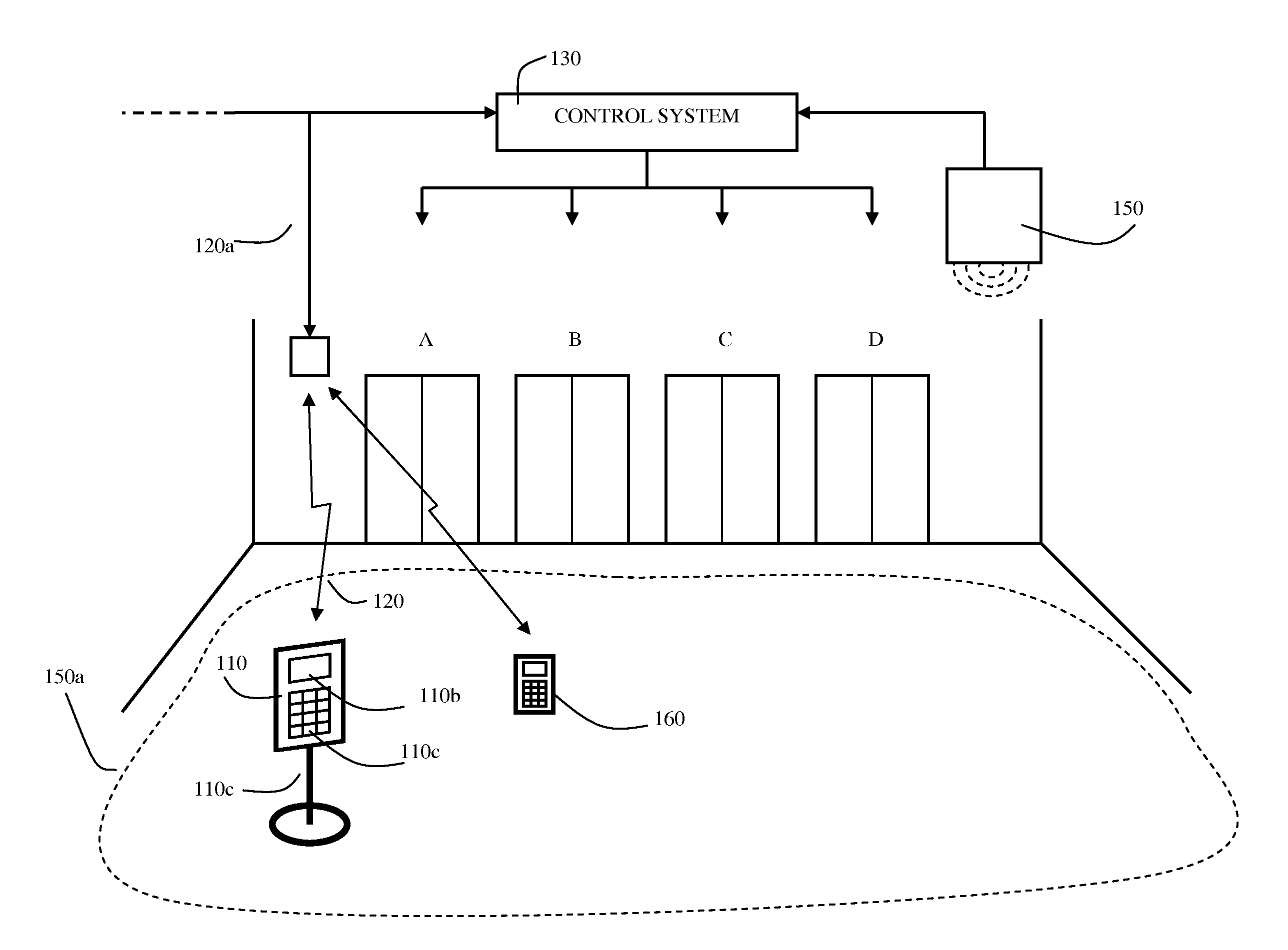
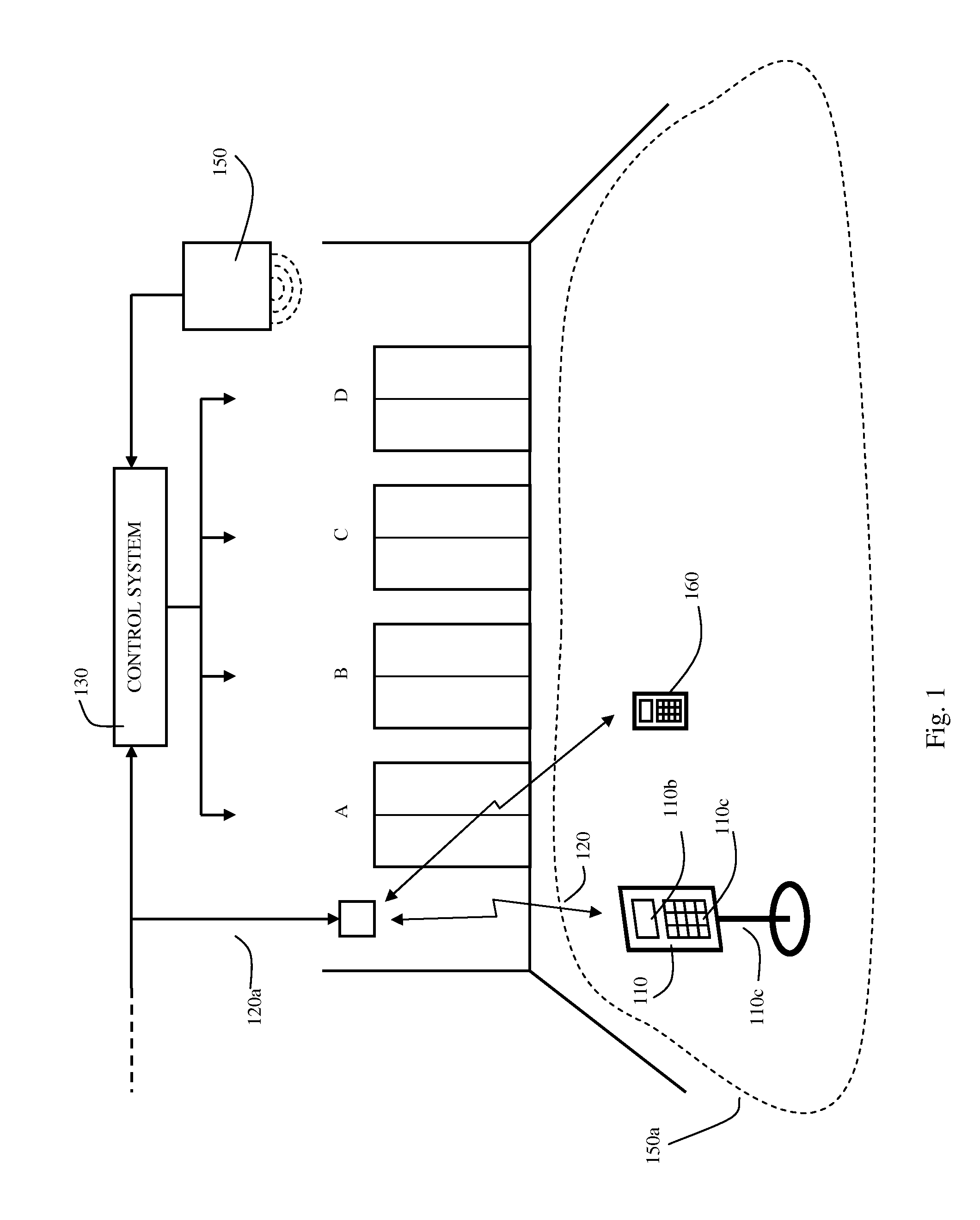
[0021]FIG. 1 presents an elevator system, in which the solution according to the invention is applied. The elevator system comprises four elevators (A, B, C, D), a control system 130, and also a portable call terminal 110. The call terminal is disposed e.g. in the entrance lobby of floor 1 and is connected to the control system 130 via a wireless data transfer connection 120. Portable call terminals can also be on other floors served by the elevator system, which are connected wirelessly in the manner of call terminal 110 to the control system 130. The elevator system can also comprise conventional call-giving appliances (up / down pushbuttons and / or destination call terminals) permanently installed on the floor levels, which passengers can use for giving calls on floor levels that do not have portable call terminals 110. In FIG. 1 the wireless data transfer connection 120 is implemented e.g. via a wireless local area network 120a, but from the standpoint of the invention any wireless...


PUM


Abstract

The present invention discloses a solution for adapting the control functions in elevator systems, wherein portable call terminals are used for the giving of calls. When the call terminals have been disposed in the desired locations in the building, the values of the control parameters that are dependent on the location of the call terminals and are used in the control of the elevator system are set.

Description

CROSS REFERENCE TO RELATED APPLICATIONS[0001]This application is a continuation of International Application Number PCT / FI2011 / 050211 filed Mar. 11, 2011 and claims priority to Finish Application Number 20100112 filed Mar. 12, 2010, the entire contents of each of which are hereby incorporated herein by reference.FIELD OF THE INVENTION[0002]The invention relates to elevator systems. More particularly the invention relates to the adaptation of the operation of an elevator system when using portable call terminals for the giving of calls.BACKGROUND OF THE INVENTION[0003]In conventional elevator systems the giving of calls occurs with up / down pushbuttons in the elevator lobbies, by means of which pushbuttons a passenger orders an elevator to his / her departure floor and, after the elevator has reached the departure floor, indicates in the elevator car his / her desired destination floor. Alongside the call-giving method in question also so-called destination call systems are used, in which...

Claims


Application Information

Patent Timeline
IPC IPC(8): B66B1/18
CPCB66B1/468B66B19/007B66B2201/4653B66B2201/4615
Inventor SARJANEN, JUKKA-PEKKASUSI, TUOMASELOMAA, NIKO
Owner KONE CORP
Why Eureka
Try Eureka