
Inverter-integrated driving module and manufacturing method therefor

a driving module and inverter-integrated technology, applied in the field of driving modules, can solve the problems of increased wiring length between the power module and the motor, increased cost, and copper loss due to the wiring in question, so as to reduce the number of connections between the phase coils, reduce the complexity of connecting work, and reduce the cost

Active Publication Date: 2012-12-20
MITSUBISHI ELECTRIC CORP
View PDF10 Cites 14 Cited by
  • Summary
  • Abstract
  • Description
  • Claims
  • Application Information

AI Technical Summary

Benefits of technology

[0004]However, in conventional power module-integrated motors, because respective output wires of the motor winding are led around an end surface of the stator to be connected to the power terminals of the power module that is inserted into and fixed to the power module mount portion that is formed by cutting away the radially outer side of the stator axially, one disadvantage has been that wiring length between the power module and the motor is increased, increasing copper loss due to the wiring in question.
[0007]The present invention aims to solve the above problems and an object of the present invention is to provide an inverter-integrated driving module and a manufacturing method therefor that can reduce copper loss by configuring phase coils by winding a conductor wire into concentrated windings consecutively on a plurality of circumferentially consecutive tooth portions, and by disposing inverter units so as to face the phase coils axially in close proximity, to reduce the number of connections between the phase coils and also to shorten wiring length between an inverter module and a motor.Means For Solving the Problem
[0009]According to the present invention, because each of the M phase coils is configured into a concentrated winding coil in which a conductor wire is wound into a concentrated winding consecutively on L circumferentially consecutive tooth portions (where L is an integer that is greater than or equal to 2), the number of connections between the phase coils is reduced, reducing complicated connecting work between the phase coils, and enabling costs to be reduced.

Problems solved by technology

However, in conventional power module-integrated motors, because respective output wires of the motor winding are led around an end surface of the stator to be connected to the power terminals of the power module that is inserted into and fixed to the power module mount portion that is formed by cutting away the radially outer side of the stator axially, one disadvantage has been that wiring length between the power module and the motor is increased, increasing copper loss due to the wiring in question.
Thus, because the number of connections between the phase coils is extremely large, another disadvantage has been that complicated connecting work is increased, giving rise to cost increases.

Method used


Image

  • Inverter-integrated driving module and manufacturing method therefor
  • Inverter-integrated driving module and manufacturing method therefor
  • Inverter-integrated driving module and manufacturing method therefor

Examples


embodiment 1

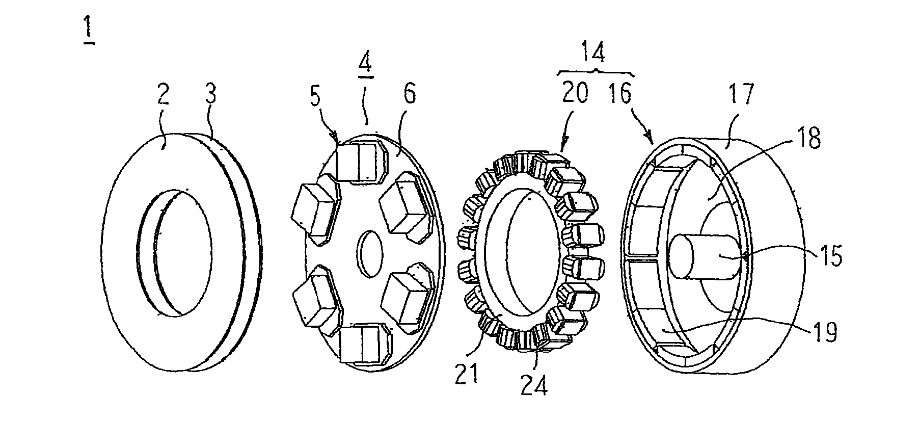
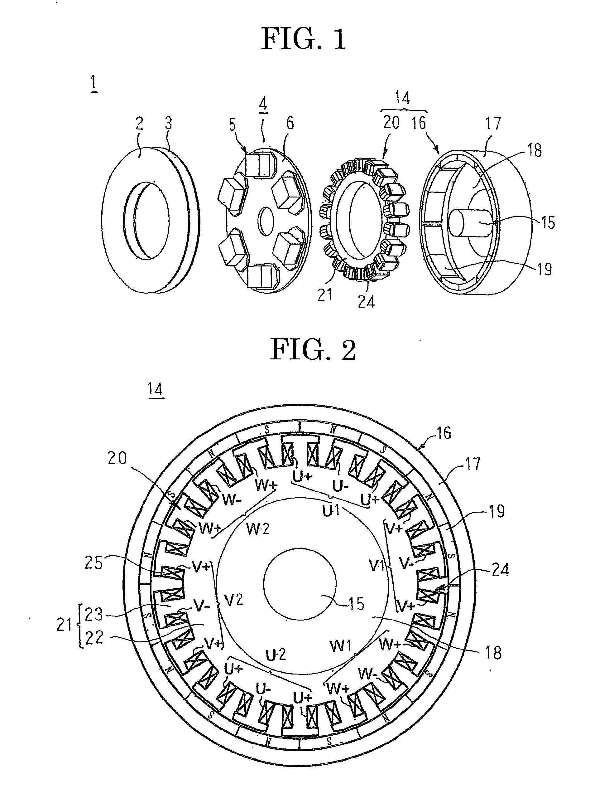
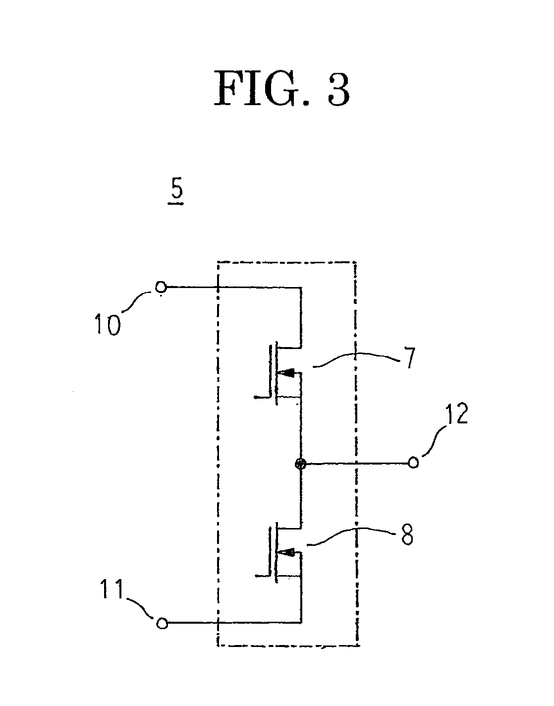
[0024]FIG. 1 is an exploded perspective that shows an inverter-integrated driving module according to Embodiment 1 of the present invention, FIG. 2 is a schematic diagram that explains a configuration of a motor that is used in the inverter-integrated driving module according to Embodiment 1 of the present invention, FIG. 3 is a schematic diagram that explains a configuration of a 2-in-1 inverter unit that is used in the inverter-integrated driving module according to Embodiment 1 of the present invention, and FIG. 4 is a circuit diagram of the inverter-integrated driving module according to Embodiment 1 of the present invention.

[0025]In FIG. 1, an inverter-integrated driving module 1 includes: a positive electrode electric supply board 2 and a negative electrode electric supply board 3 that are connected to an external direct-current (DC) power supply to constitute a DC supply line; an inverter module 4 that converts the direct-current power that is supplied to the positive electro...

embodiment 2

[0048]FIG. 5 is a circuit diagram of the inverter-integrated driving module according to Embodiment 2 of the present invention.

[0049]In FIG. 5, a stator coil 26 is constituted by a first three-phase alternating-current winding 26A and a second three-phase alternating-current winding 26B that are each delta-connected. Specifically, the first three-phase alternating-current winding 26A is configured into a mesh-connected coil by connecting a winding finish end portion of a U1-phase phase coil 25 to a winding start end portion of a V1-phase phase coil 25, connecting a winding finish end portion of the V1-phase phase coil 25 to a winding start end portion of a W1-phase phase coil 25, and connecting a winding finish end portion of the W1-phase phase coil 25 to a U1-phase winding start end portion. Similarly, the second three-phase alternating-current winding 26B is configured into a mesh-connected coil by connecting a winding finish end portion of a U2-phase phase coil 25 to a winding st...

embodiment 3

[0052]FIG. 6 is a schematic diagram that explains a method for connecting a stator coil in an inverter-integrated driving module according to Embodiment 3 of the present invention. Moreover, a rotor is omitted from FIG. 6 in order to facilitate explanation.

[0053]In FIG. 6, a neutral-point lead wire 27 that is configured using winding finish portions of U1-phase, V1-phase, and W1-phase phase coils 25 that constitute a first three-phase alternating-current winding is led out at a first axial end of the stator 20, in addition, a neutral-point lead wire 27 that is configured using winding finish portions of U2-phase, V2-phase, and W2-phase phase coils 25 that constitute a second three-phase alternating-current winding is led out at the first axial end of the stator core 21, and is joined by solder, etc., to an annular linking body 29 that is made of an electrically-conductive material that is disposed at the first axial end of the stator 20. Output wires 28 that are configured using win...


PUM

PropertyMeasurementUnit
Timeaaaaaaaaaa
Forceaaaaaaaaaa
Forceaaaaaaaaaa

Abstract

Phase coils are each configured by winding a conductor wire in a concentrated winding consecutively on three circumferentially consecutive tooth portions, six inverter units of an inverter module are each disposed in close proximity to a motor so as to face each of the phase coils axially, and the motor and the inverter module are electrically connected by connecting an alternating-current output terminals of each of the plurality of inverter units to output wires of the phase coils that face the inverter units axially.

Description

TECHNICAL FIELD[0001]The present invention relates to a driving module in which an inverter is internally mounted and to a manufacturing method therefor.BACKGROUND ART[0002]In conventional power module-integrated motors, a power module is inserted into and fixed to a power module mount portion that is formed by cutting away a stator axially such that power terminals and controlling terminals project externally, the power terminals are connected to a motor winding, the controlling terminals are connected to an external controlling circuit, and a rotor core is configured so as to rotate by means of switching of the power module by sending signals from the external controlling circuit (see Patent Literature 1, for example).CITATION LISTPatent Literature[0003]Patent Literature 1: Japanese Patent Laid-Open No. 2004-236470 (Gazette)SUMMARY OF THE INVENTIONProblem To Be Solved By the Invention[0004]However, in conventional power module-integrated motors, because respective output wires of ...

Claims


Application Information

Patent Timeline
IPC IPC(8): H02K11/00H02K15/02
CPCH02K11/0073B60L11/1803Y10T29/49009Y02T10/641B60L2200/26Y02T10/7005H02K11/33B60L50/51Y02T10/64Y02T10/70H02K11/02
Inventor HAZEYAMA, MORIYUKIMIYAMA, YOSHIHIROINOUE, MASAYAOBIRAKI, YOSHIKOKITAMURA, TATSUYA
Owner MITSUBISHI ELECTRIC CORP
Learn More