
Digital pll with automatic clock alignment

a digital pll and automatic clock technology, applied in the direction of automatic control, electrical equipment, etc., can solve the problems of affecting the transmission quality of the transmitted carrier signal and the receiver's carrier signal, and causing the transmission quality to suffer

Inactive Publication Date: 2012-12-20
INTEL CORP
View PDF13 Cites 46 Cited by
  • Summary
  • Abstract
  • Description
  • Claims
  • Application Information

AI Technical Summary

Problems solved by technology

During the transmission of a wireless signal, the frequency and phase of the wireless signal may become distorted resulting in differences between the transmitted carrier signal and a receiver's carrier signal.
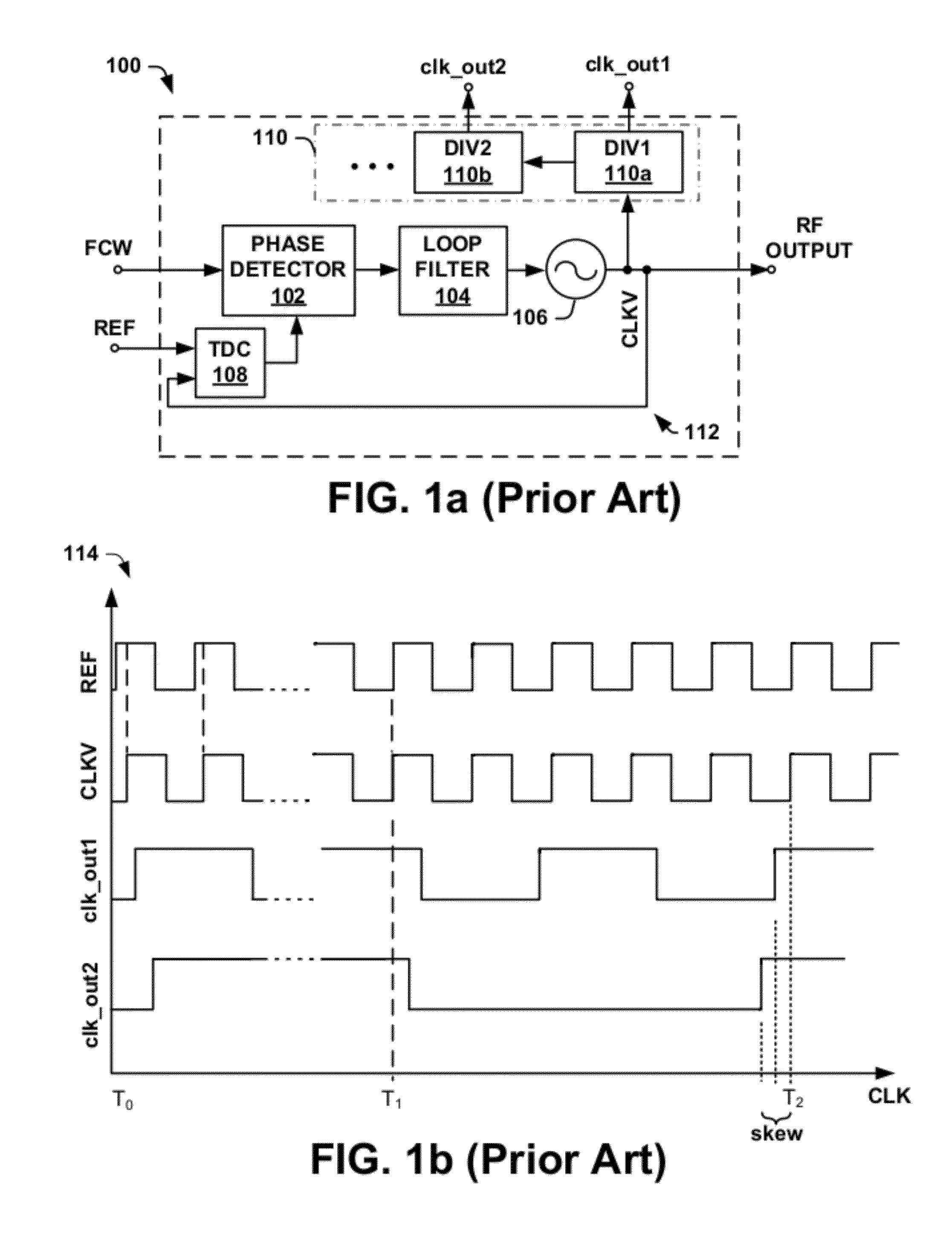
The clock signals exhibit a clock skew around time T2, which can be detrimental to the transmission quality of signals transmitted using polar modulation transmission chains, where close alignment between amplitude modulation (AM) and phase / frequency modulation (PM / FM) paths is required for proper operation.

Method used


Image

  • Digital pll with automatic clock alignment
  • Digital pll with automatic clock alignment
  • Digital pll with automatic clock alignment

Examples


Embodiment Construction

[0022]The present invention will now be described with reference to the attached drawing figures, wherein like reference numerals are used to refer to like elements throughout, and wherein the illustrated structures and devices are not necessarily drawn to scale.

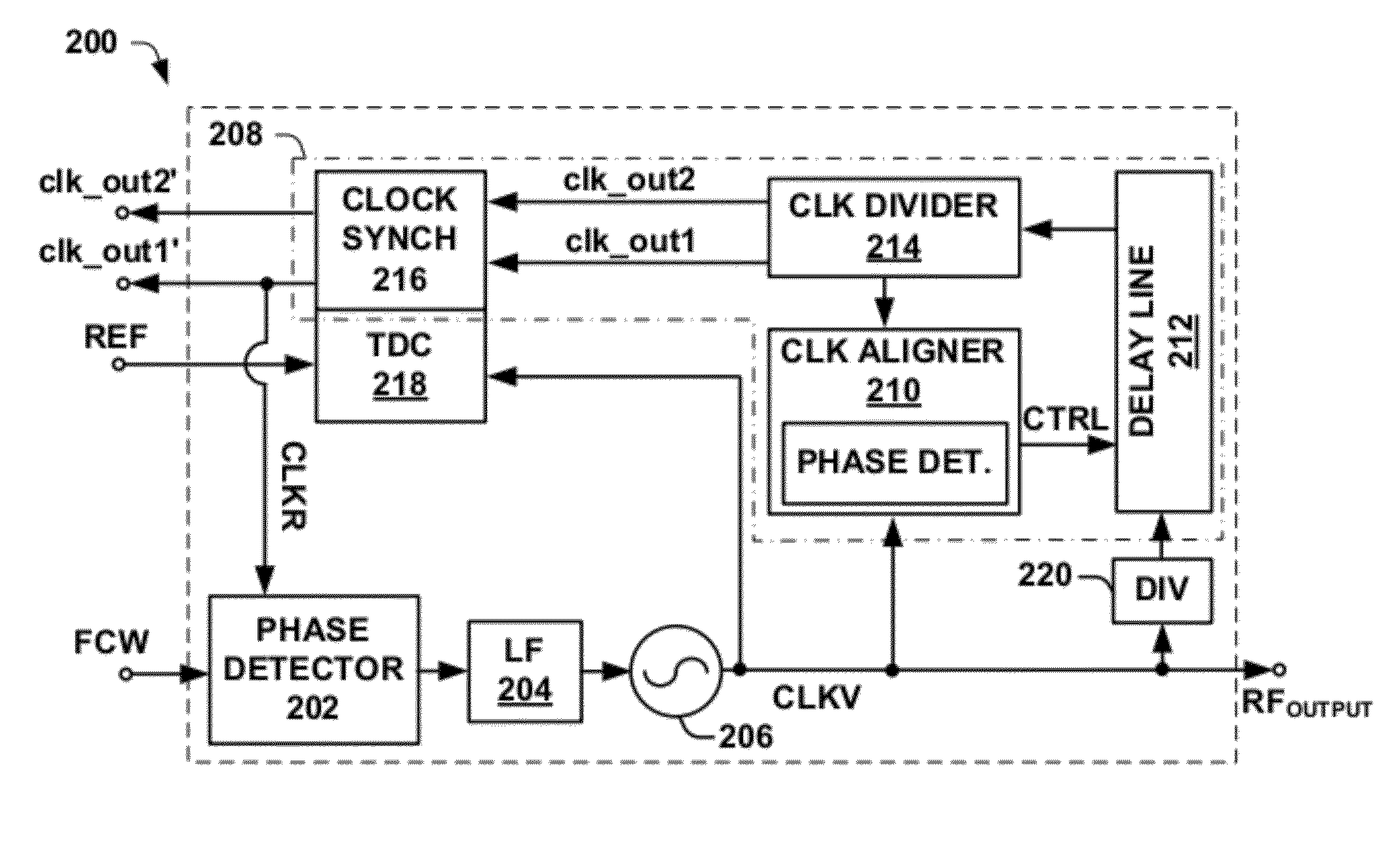
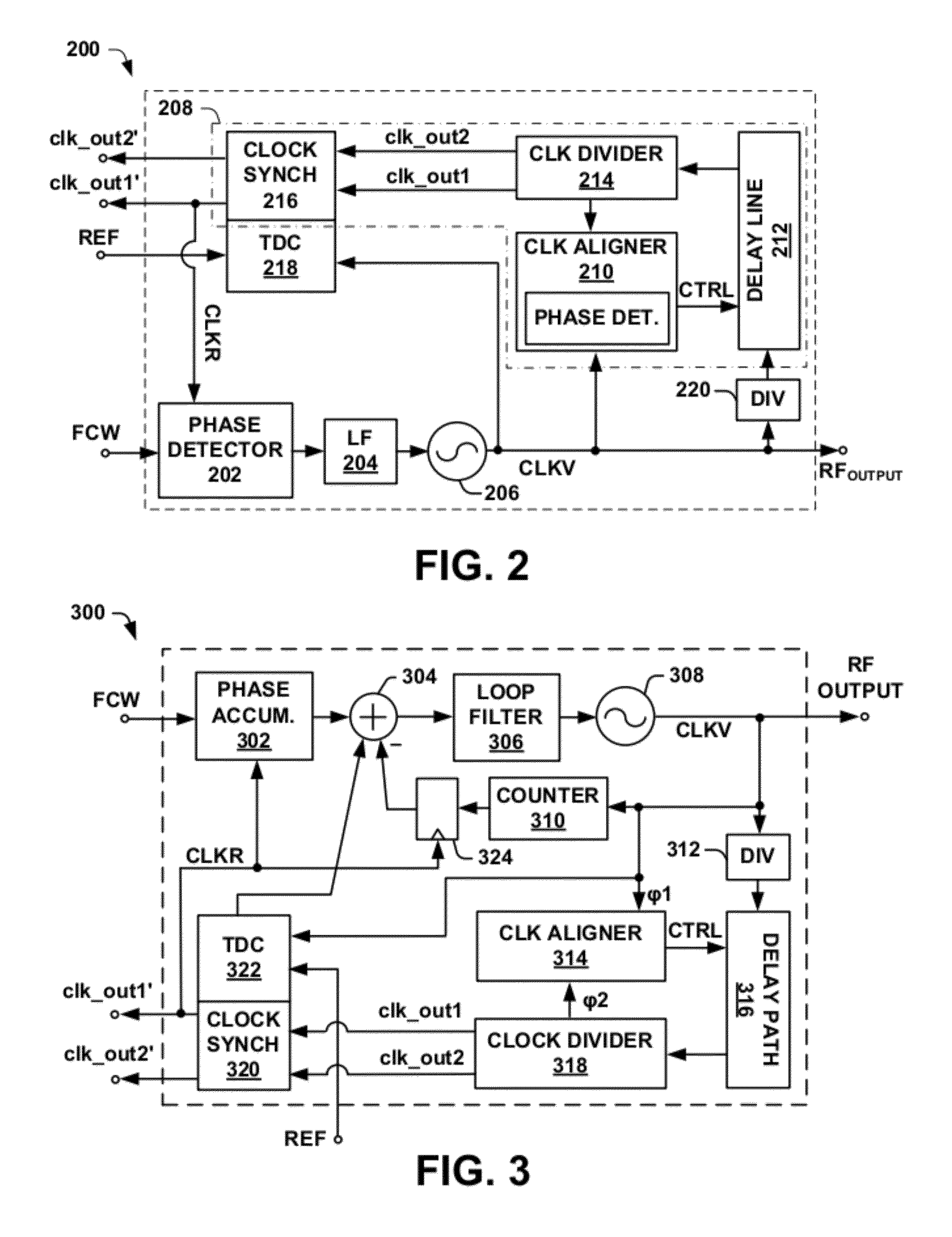
[0023]Some aspects of the present disclosure provide for a digital phase locked loop (ADPLL) having a delay alignment element that generates a plurality of time-aligned clock signals spanning a plurality of different clock domains (e.g., having different frequency values). In one embodiment, the method and apparatus comprise a digital phase locked loop having a digital controlled oscillator (DCO) configured to generate a variable clock signal that is separated into two separate signal paths operating according to two separate clock domains. A first signal path is configured to generate a PLL feedback signal that synchronizes the variable clock signal with a reference signal. A second signal path comprises a clock divider cir...


PUM


Abstract

One embodiment of the present invention relates to a digital phase locked loop (ADPLL) configured to generate a plurality of time-aligned output clock signals having different frequency values. The ADPLL comprises a digital controlled oscillator configured to generate a variable clock signal that is separated into two signal paths operating according to two separate clock domains. A first signal path is configured to generate a feedback signal that synchronizes the variable clock signal with a reference signal. A second signal path comprises a clock divider circuit configured to synchronously divide the variable clock signal to automatically generate a plurality of time-aligned output clock signals having different frequencies. A clock aligner monitors a phase difference between the variable clock signal and one of the plurality of time-aligned output clock signals and generates a control signal that causes a programmable delay line to automatically time-align the output clock signals with the variable clock signal.

Description

BACKGROUND OF THE INVENTION[0001]Phase locked loops (PLLs) are important components of many modern day communication circuits. During the transmission of a wireless signal, the frequency and phase of the wireless signal may become distorted resulting in differences between the transmitted carrier signal and a receiver's carrier signal. PLLs enable synchronization between the receiver's carrier signal and the transmitted carrier signal by regulating the phase and frequency of carrier signals used within a device according to a reference signal.[0002]FIG. 1a illustrates a simplified block diagram of an exemplary phase locked loop (PLL) 100. The PLL 100 comprises a digitally controlled oscillator (DCO) 106 configured to generate a digital variable clock signal (CLKV) in the RF frequency band, which is provided to a divider chain 110 and a feedback path 112.[0003]The divider chain 110 is configured to divide the variable clock signal CLKV to generate a plurality of output clock signals ...

Claims


Application Information

Patent Timeline
IPC IPC(8): H03L7/06
CPCH03L7/183
Inventor THALLER, EDWINMARSILI, STEFANOLI PUMA, GIUSEPPE
Owner INTEL CORP
Learn More