Scanning Microscope and Method for Light-Microscopic Imaging of an Object

a scanning microscope and object technology, applied in the field of scanning microscopes, can solve the problems of not being able to place spherical objects in collision-free positions under such a right-angled arrangement of objectives, shading by surrounding tissue, and unable to image certain biological objects, etc., to achieve high spatial resolution and large surface area

Active Publication Date: 2012-12-20
LEICA MICROSYSTEMS CMS GMBH
View PDF1 Cites 26 Cited by
  • Summary
  • Abstract
  • Description
  • Claims
  • Application Information

AI Technical Summary

Benefits of technology

[0030]This advantageous embodiment takes advantage of the fact that STED depletion is not necessary, and even unwanted, in the plane in which the illumination focus is moved to generate the light sheet. In the approach of the present invention, the intention is to generate a light sheet that has as large a surface area as possible and, at the same time, is as thin as possible to be able to acquire cross-sectional images with high spatial resolution. The area of the light sheet is determined by the length of the moving illumination focus, while the thickness of the sheet is determined by the extent of the illumination focus transverse to the plane in which the illumination focus is moved. The aforedescribed depletion focus is specifically shaped to reduce the excitation effect of the excitation focus only in the direction of the transverse extent of the focus, but not in the direction of its longitudinal extent.
[0031]It is conceivable to equip the scanning microscope of the present invention with an element serving to vary the intensity of the illuminating light beam within a scanning period during which the illumination focus is moved across the target region. This embodiment uses the fact that the light sheet illuminating the target region is sequentially generated by the moving illumination focus. This makes it possible to achieve modulated or patterned illumination of the target region. To this end, the intensity of the illuminating light beam is varied within the scanning period during which the illumination focus scans across the target region. In this way, the intensity of the illuminating light beam can be adjusted as desired at any point of time within the scanning period, and thus, at any position of the target region. The element used for varying the intensity of the illuminating light beam within the scanning period may be, for example, an acousto-optic tunable filter (AOTF), an acousto-optic modulator (AOM), or an electro-optic modulator (EOM).

Problems solved by technology

This arrangement of the objectives, where the illumination axis and the observation axis are perpendicular to each other, can be a disadvantage in the imaging of certain biological objects.
For example, it is often not possible to place spherical objects in a collision-free position under such a right-angled arrangement of objectives.
In such situations, the conventional arrangement of objectives frequently results in shading by surrounding tissue.

Method used


Image

  • Scanning Microscope and Method for Light-Microscopic Imaging of an Object
  • Scanning Microscope and Method for Light-Microscopic Imaging of an Object
  • Scanning Microscope and Method for Light-Microscopic Imaging of an Object

Examples


Embodiment Construction

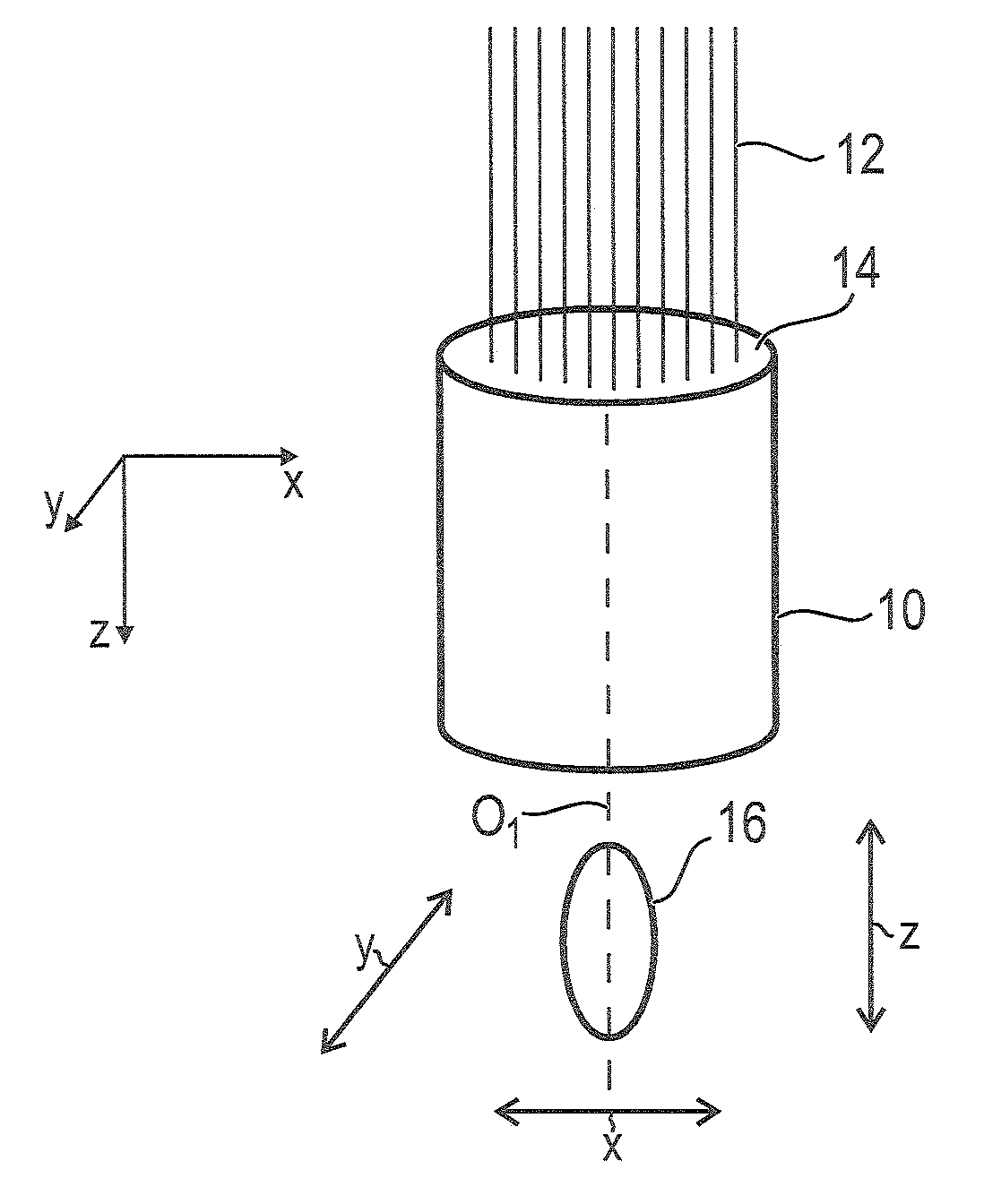
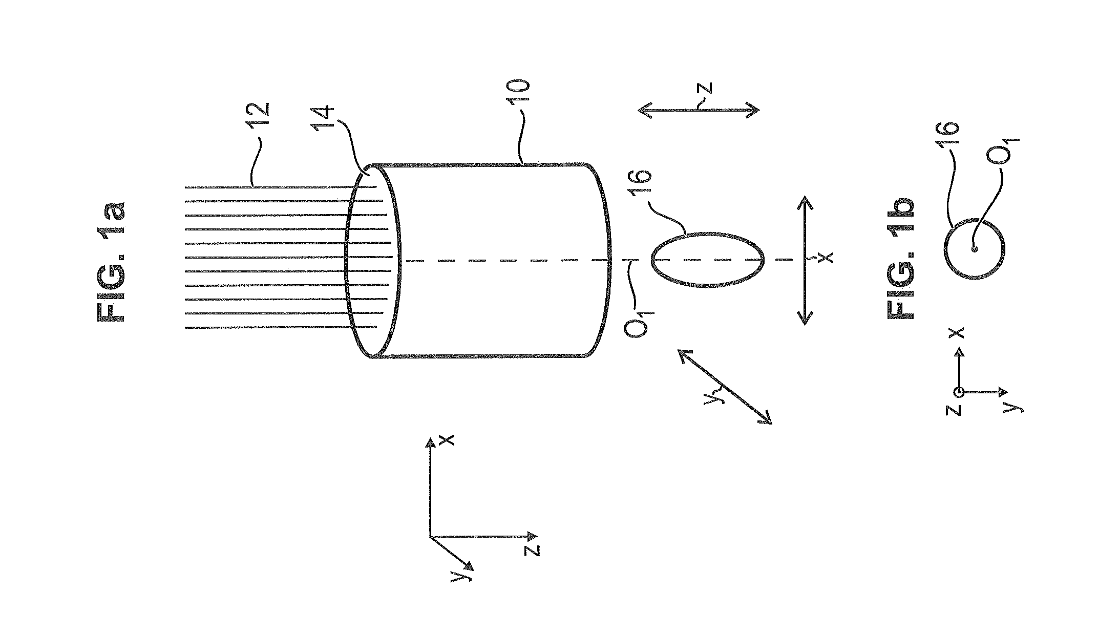
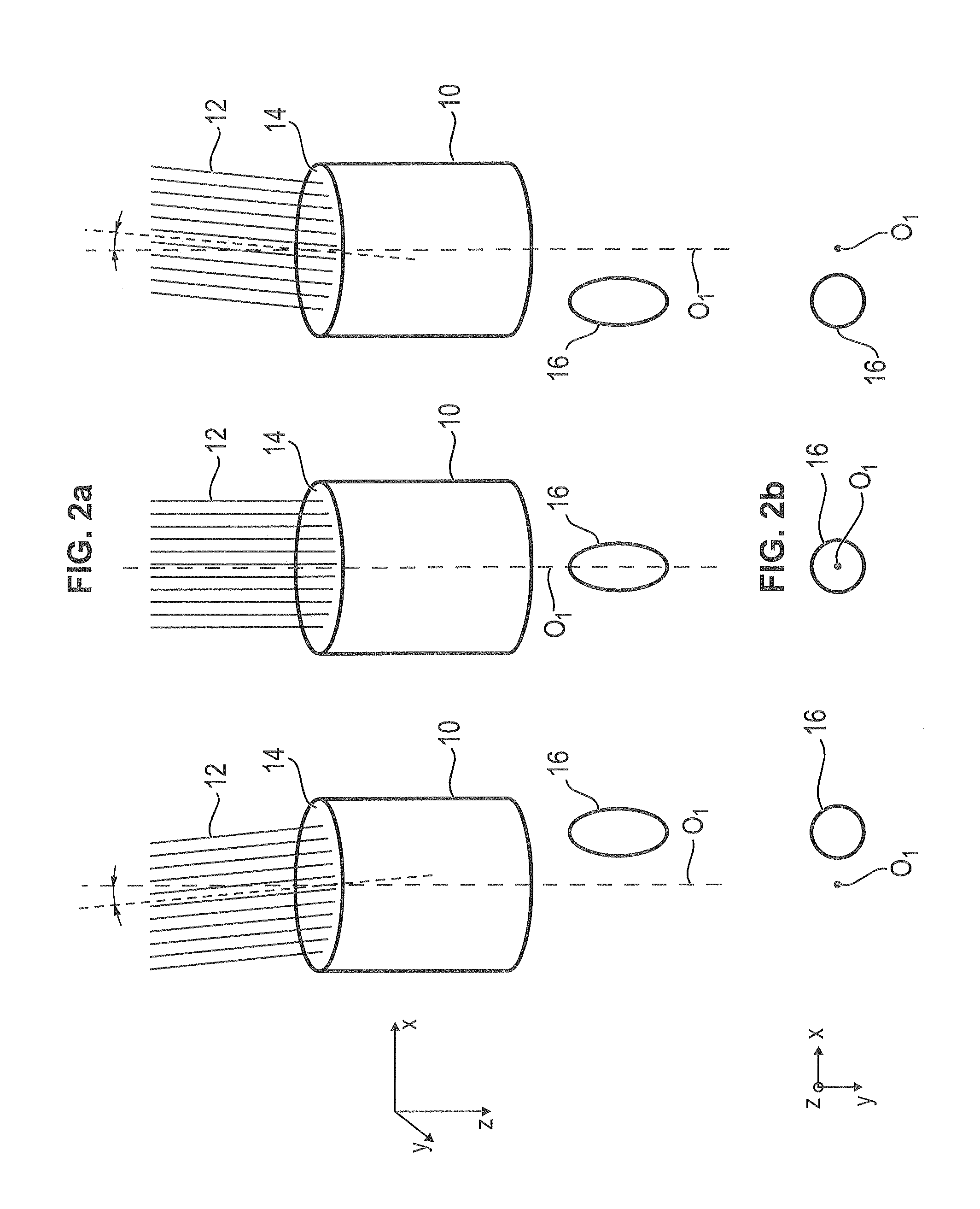
[0054]The principle of off-center underillumination of the [entrance] pupil according to the present invention will now be described with reference to FIGS. 1 through 4. In particular, it will be described how, according to the present invention, illumination optics 10 produce an illumination focus 16 from an illuminating light beam 12 incident on an entrance pupil of illumination optics 10. In this connection, it should be noted that the above-mentioned figures are purely schematic and are merely intended to facilitate the understanding of the present invention.

[0055]Referring first of all to FIG. 1a, the bundle of rays constituting illuminating light beam 12 uses the full aperture of illumination optics 10; i.e., passes through the entire area of entrance pupil 14 of illumination optics 10, which is typical in conventional point-by-point confocal scanning. In FIG. 1a, the optical axis of illumination optics 10 is denoted by O1. In the case depicted in FIG. 1a, illuminating light b...


PUM


Abstract

A scanning microscope includes a light source, illumination optics, and a scanning device for moving the illumination focus across a target region and doing so by varying the direction of incidence in which the illuminating beam enters an entrance pupil of the illumination optics. To incline the illumination focus relative to the optical axis of the optics, the scanning device directs the illuminating beam onto a portion of the entrance pupil that is offset from the center of the pupil and, in order to move the illumination focus across the target region, the scanning device varies the direction of incidence of the illuminating beam within said portion. An observation objective is provided which is spatially separated from the illumination optics and disposed such that its optical axis (O3) is substantially perpendicular to the target region and at an acute angle (α) to the optical axis (O1) of the illumination optics.

Description

RELATED APPLICATIONS[0001]This application claims priority to German Patent Application No. 102011051042.7 filed on Jun. 14, 2011, which is incorporated herein by reference in its entirety.FIELD OF THE INVENTION[0002]The present invention relates to a scanning microscope having a light source for emitting an illuminating light beam, illumination optics for producing an elongated illumination focus in an object to be imaged, and a scanning device for moving the illumination focus across a target region to be illuminated of the object to be imaged and doing so by varying the direction of incidence in which the illuminating light beam enters an entrance pupil of the illumination optics.BACKGROUND OF THE INVENTION[0003]In the prior art, scanning microscopes have been proposed which are used, for example, in fluorescence microscopy to excite dyes by laser light to emit fluorescent radiation, which is then captured by a detector to form an image of the object to be examined. The microscop...

Claims


Application Information

Patent Timeline
Patent Type & Authority Applications(United States)
IPC IPC(8): G02B21/06G02B26/10
CPCG02B21/0032G02B21/0076G02B21/10G02B21/16G02B21/367
Inventor KNEBEL, WERNERULRICH, HEINRICH
Owner LEICA MICROSYSTEMS CMS GMBH
Why Eureka
Try Eureka