Wireless transmitter/receiver, wireless communication device, and wireless communication system

a wireless communication and wireless communication technology, applied in the field of wireless communication devices and systems, can solve the problems of increasing power consumption, prolonging the life of the battery, and increasing the use of the pll circui

Inactive Publication Date: 2012-12-20
PANASONIC INTELLECTUAL PROPERTY MANAGEMENT CO LTD
View PDF9 Cites 27 Cited by
  • Summary
  • Abstract
  • Description
  • Claims
  • Application Information

AI Technical Summary

Benefits of technology

[0050]With this configuration, even immediately after erroneous

Problems solved by technology

However, since a fire alarm is usually installed at a high location (e.g., the ceiling) where it is not easy to access in maintenance (e.g., battery replacement), preferably, the fire alarm can be used for a long period of time, e.g., for years, without maintenance and power consumption thereof is reduced to thereby lengthen a life span of the battery.
However, when the operation controller is in the sleep state except for the case of the fire detection, fire notification information wirelessly transmitted from another fire alarm cannot be received.
However, the use of the PLL circuit increases power consumption in comparison to the case of

Method used


Image

  • Wireless transmitter/receiver, wireless communication device, and wireless communication system
  • Wireless transmitter/receiver, wireless communication device, and wireless communication system
  • Wireless transmitter/receiver, wireless communication device, and wireless communication system

Examples


embodiment 1

[0066]A first embodiment of the present invention will be described in detail with reference to FIGS. 1 to 5. FIG. 1 illustrates a wireless communication system employing a wireless transceiver in accordance with the first embodiment of the present invention.

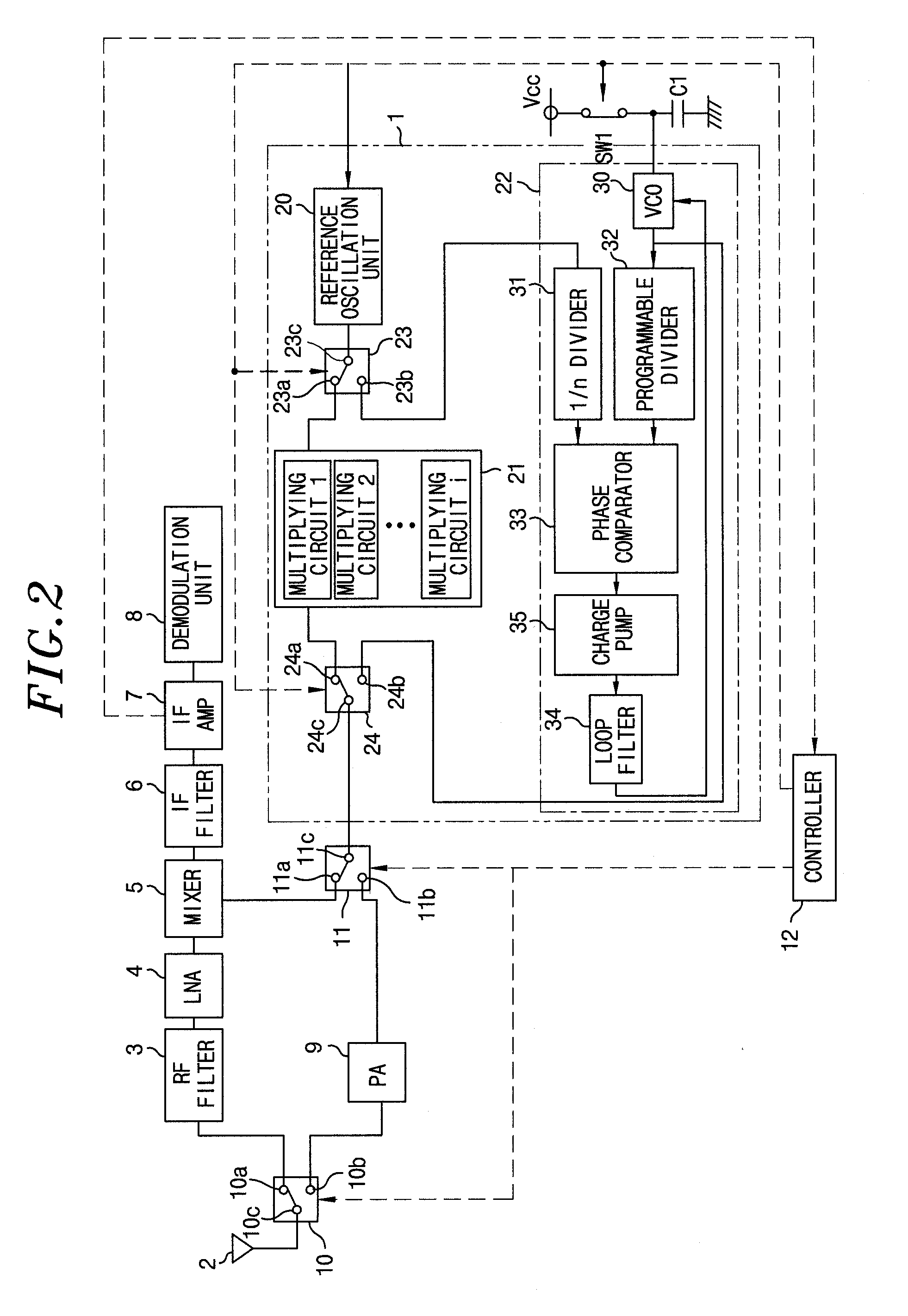
[0067]As shown in FIG. 2, the wireless transceiver (transmitter / receiver) of the present embodiment includes a local oscillator 1, an antenna 2, an RF filter 3, a low noise amplifier (LNA) 4, and a mixer 5. Further, the wireless transceiver includes an intermediate frequency (IF) filter 6, an IF amplifier 7, a demodulation unit 8, a transmission unit 9, an antenna switching unit 10, a transmission / reception switching unit 11, and a controller (which corresponds to an operation controller in FIG. 1).

[0068]Here, the wireless transceiver of the present embodiment employs, for example, a frequency modulation (frequency shift keying (FSK)) scheme as a modulation scheme. When it transmits a radio signal from the antenna 2, it executes...

second embodiment

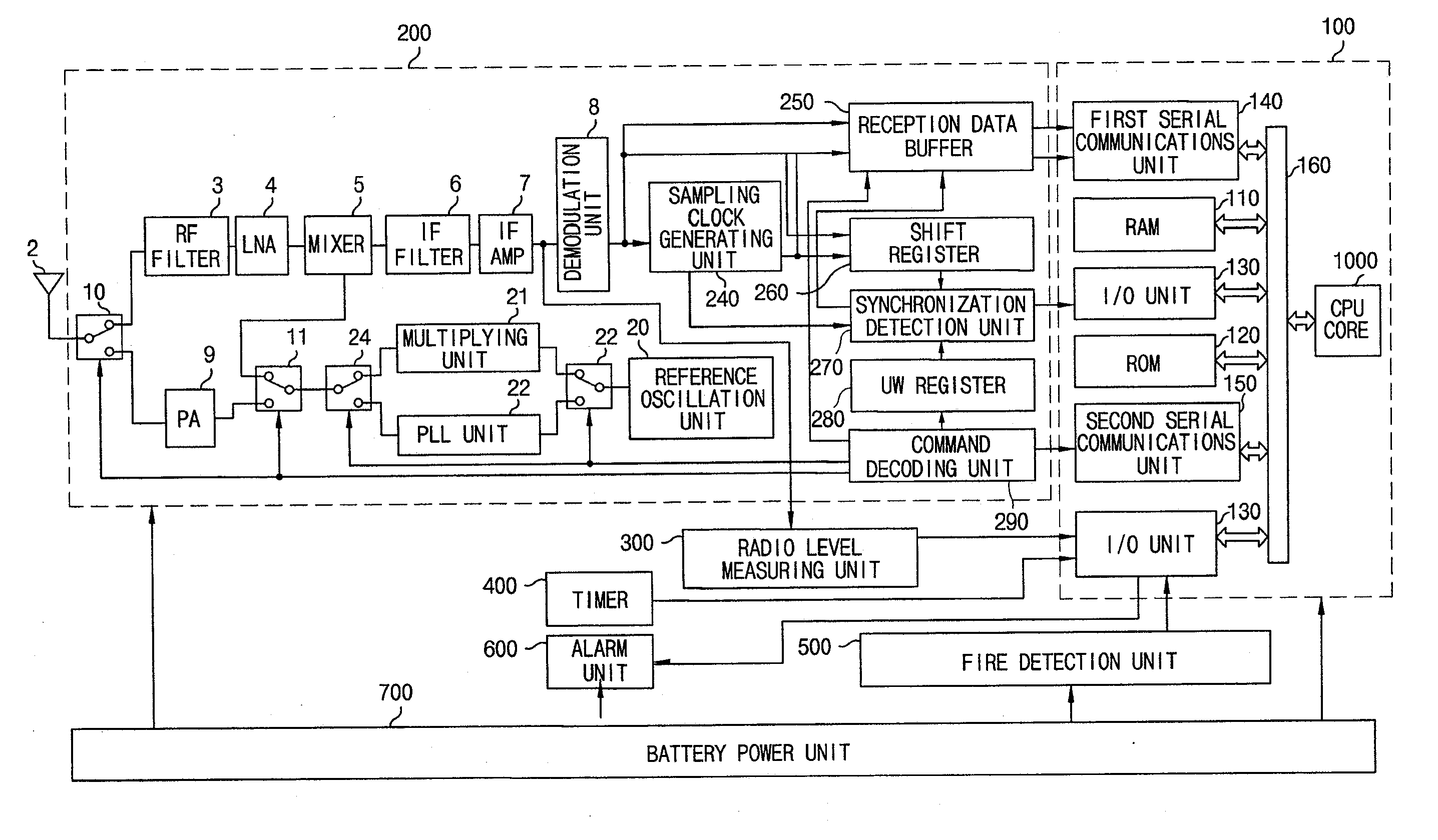
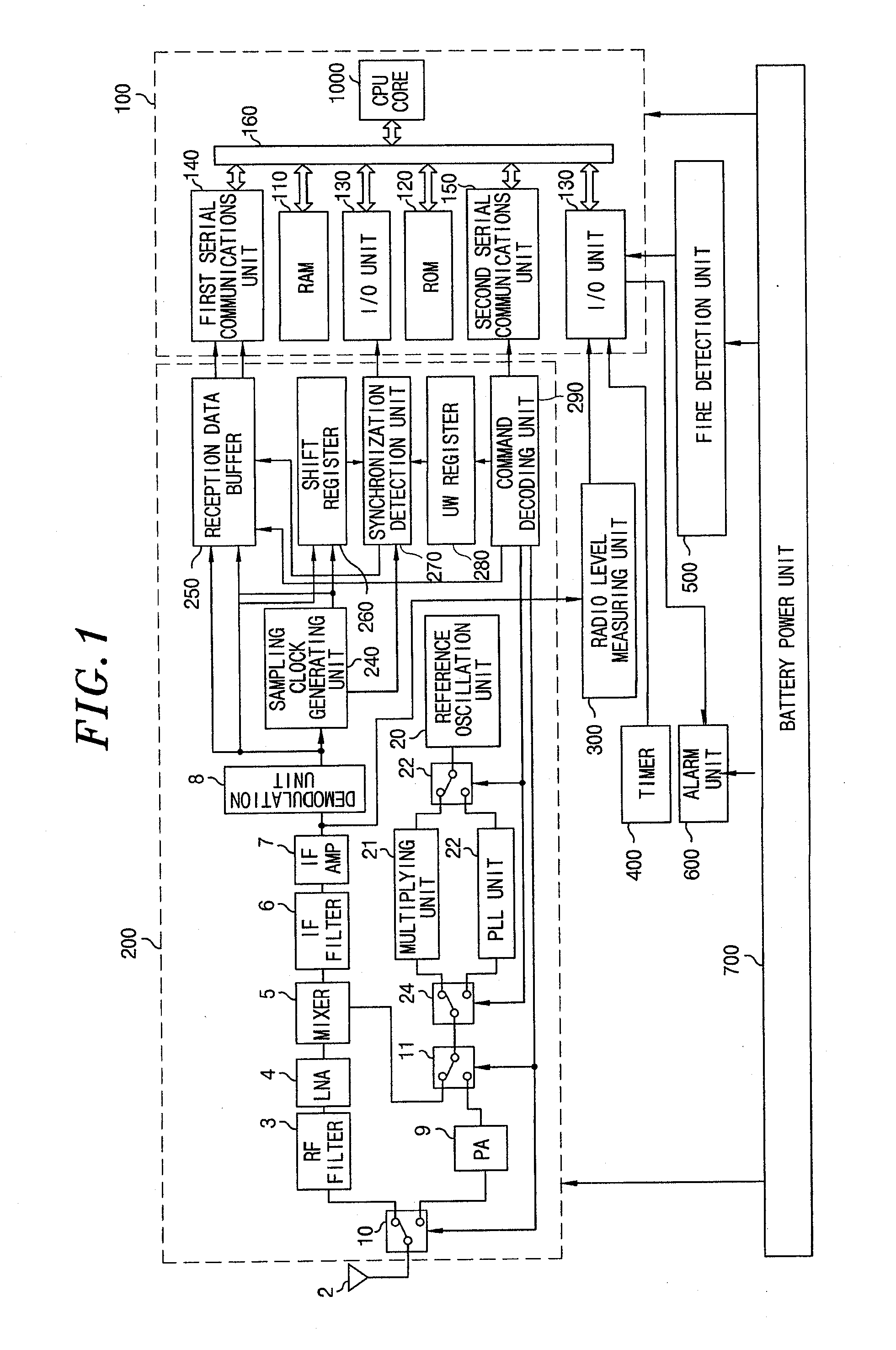
[0120]FIG. 6 is a view showing the configuration of a wireless communication system to which the second embodiment is applicable, which corresponds to a simplified illustration of FIG. 1. In the present embodiment, a fire alarm system includes multiple (two in the drawing) fire alarms TR. In the following description, respective fire alarms will be denoted by fire alarms TR1, TR2, . . . , TRn (where n is a positive integer), and in case of generally describing a fire alarm, a fire alarm TR will be denoted.

[0121]The fire alarm TR includes an operation controller 100, a wireless transmission / reception unit 200, a radio level measuring unit 300, a timer 400, a fire detection unit 500, an alarm unit 600, and a battery power unit 700.

[0122]The wireless transmission / reception unit 200 transmits a radio signal through a radio wave from an antenna 2a and receives a radio signal transmitted from a different fire alarm TR by the antenna 2a. The wireless transmission / reception unit 200 has a f...

modified embodiment of second embodiment

[0150]A modified embodiment of the wireless communication system in accordance with the second embodiment will be described with reference to FIG. 8. In the second embodiment, in case of intermittent reception, when the radio level measuring unit 300 completes measuring of a received signal strength, the radio level measuring unit 300 activates the operation controller 100 from the sleep state, such that the operation controller 100 compares the measurement result of the received signal strength with the reference value. In case of intermittent reception of the present modified embodiment, when the radio level measuring unit 300 completes measuring of a received signal strength, the radio level measuring unit 300 compares the measurement result of the received signal strength with the reference value.

[0151]Further, only when the measurement result of the received signal strength is equal to or greater than the reference value, the radio level measuring unit 300 activates the operati...


PUM


Abstract

Disclosed is a wireless transmitter/receiver provided with: a local oscillator which oscillates at a predetermined local oscillator frequency; a mixer which mixes a local oscillation signal of the local oscillation frequency outputted from an output terminal of the local oscillator and a radio signal received by an antenna; a modulation circuit which modulates the local oscillator signal and generates a radio signal; and a transmission/reception switching unit which selectively switches over between a reception state in which the output terminal of the local oscillator is connected to the mixer and a transmission state in which the output terminal is connected to the antenna without passing through the mixer.

Description

FIELD OF THE INVENTION[0001]The present invention relates to a wireless communication device and system for transmitting and receiving a radio signal between multiple wireless communications stations, and a wireless transceiver used therefor.BACKGROUND OF THE INVENTION[0002]Conventionally, there have been disclosed various types of wireless transceivers employing a superheterodyne scheme that converts a radio frequency signal into a relatively low frequency signal (intermediate frequency signal), and amplifying and detecting the same. For example, a wireless receiver disclosed in Patent Document 1 includes a local oscillator which outputs a signal (i.e., a local oscillation signal) of a frequency (local oscillation frequency) that is an integer multiple of the frequency of an input signal (reference oscillation signal).[0003]In the wireless receiver, a reception signal (RF signal) received by an antenna and the local oscillation signal outputted from the local oscillator are mixed b...

Claims


Application Information

Patent Timeline
IPC IPC(8): H04B1/44H04W52/02H04W88/02H04W24/00
CPCH04W52/0274Y02D70/00H04W52/0241Y02D30/70
Inventor UEDA, SHINSUKENAGATA, MASAHIROYOSHIKI, KAZUHISAKURITA, MASANORISUZUKI, JUNICHI
Owner PANASONIC INTELLECTUAL PROPERTY MANAGEMENT CO LTD
Why Eureka
Try Eureka