
Pump controller

a technology of pump controller and controller, which is applied in the direction of process and machine control, positive displacement liquid engine, instruments, etc., can solve the problems of arcing and scorching between the contacts of the switch, and the mechanical switch has several limitations, so as to reduce the dependency. only

Active Publication Date: 2012-12-20
XYLEM IP HLDG
View PDF1 Cites 1 Cited by
  • Summary
  • Abstract
  • Description
  • Claims
  • Application Information

AI Technical Summary

Benefits of technology

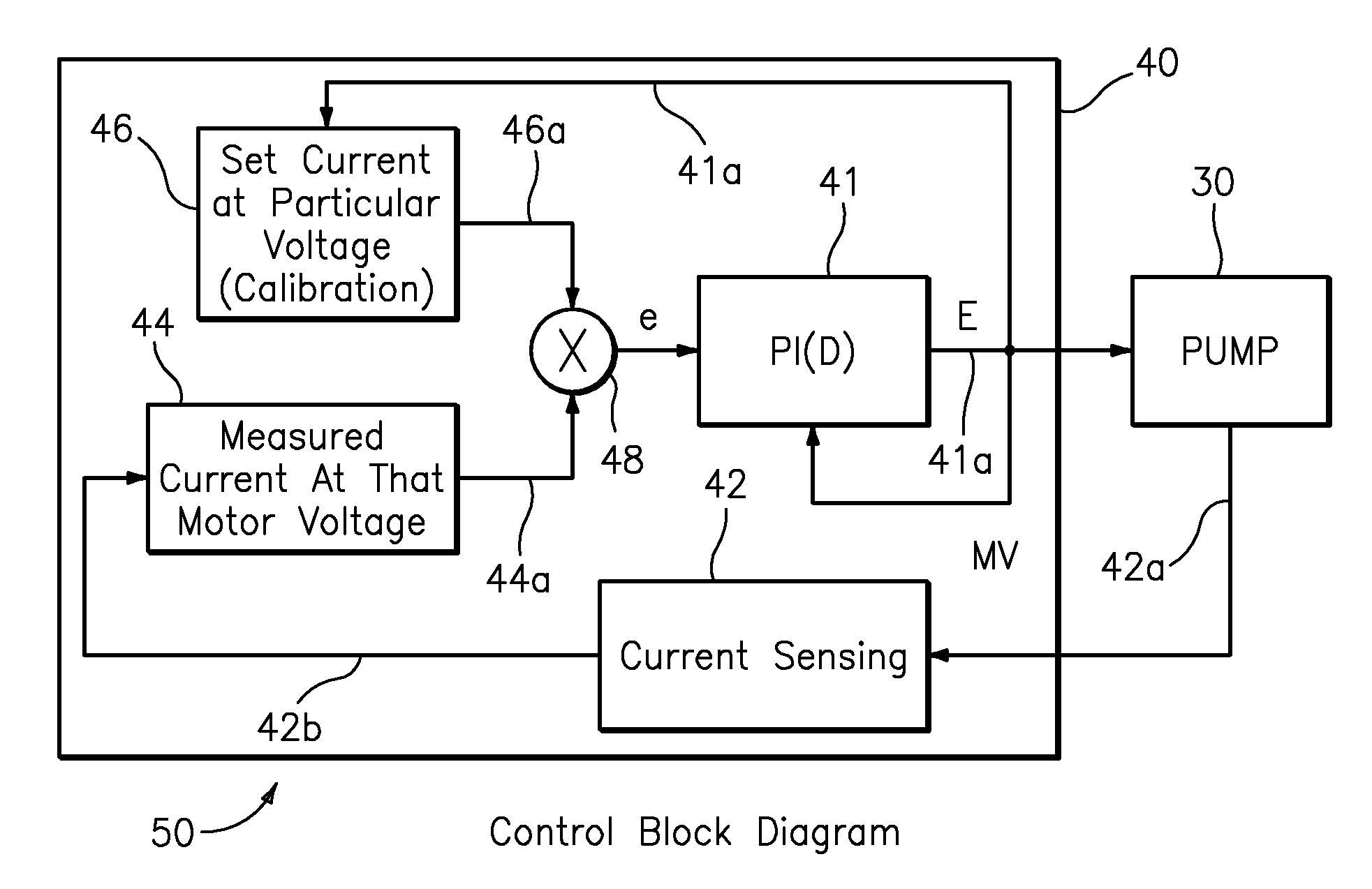
[0007]To overcome the aforementioned problems with the mechanical pressure switch and pressure sensor, a new technique is provided using current sensing to control the pressure at a constant level without the direct sensing of the pressure. This new technique will help to reduce the dependency solely on the pressure switch or sensor and their non linearity and other associated problems such as the non-repetitive behavior, as well as other known problems associated with being affected by electromagnetic interference (EMI), etc.

Problems solved by technology

Mechanical switches have several limitations.
For example, during the repeated opening and closing of the pump's power circuit, arcing and scorching often occurs between the contacts of the switch.

Method used


Image

  • Pump controller
  • Pump controller
  • Pump controller

Examples


Embodiment Construction

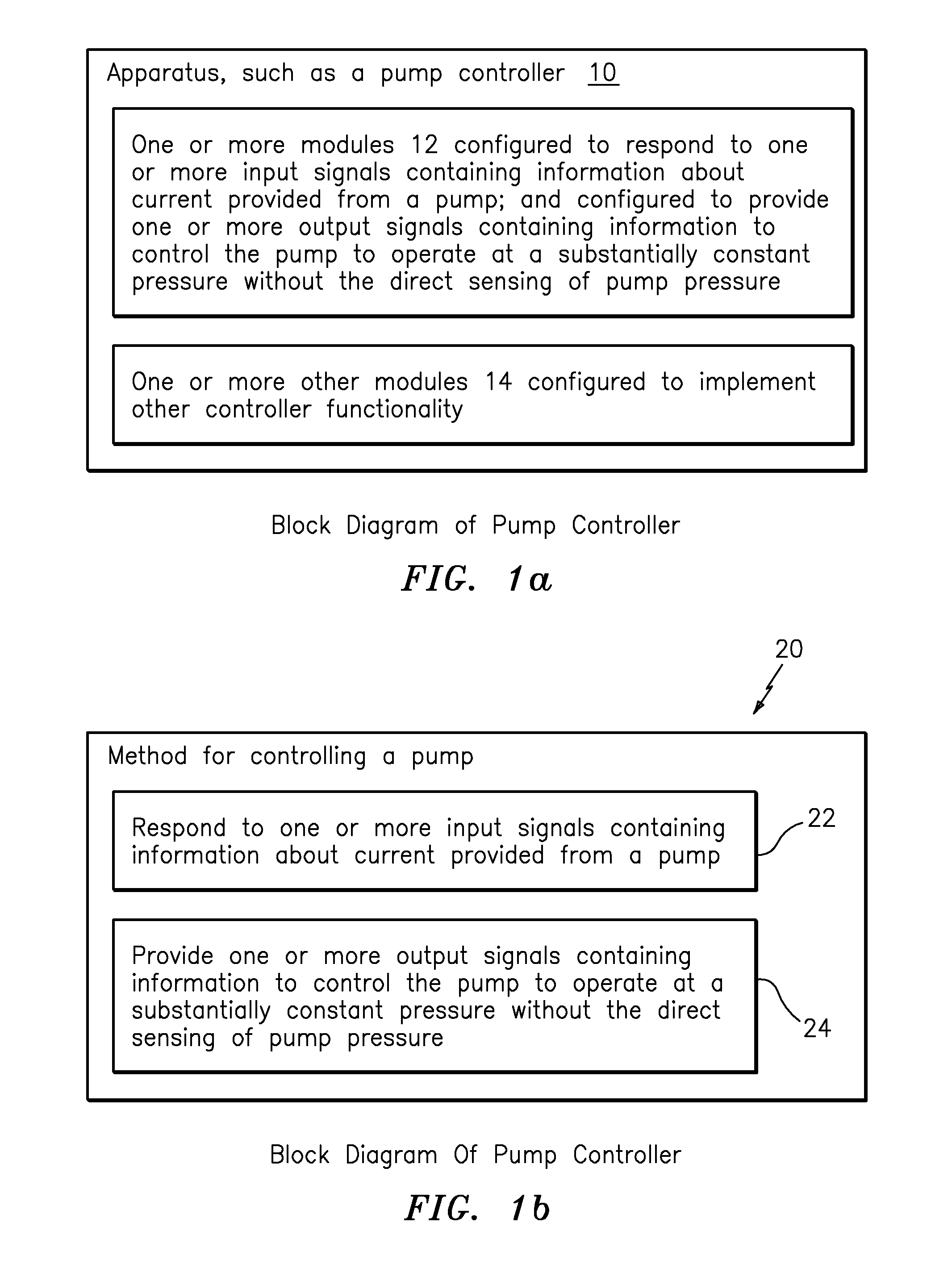
[0026]FIGS. 1a shows apparatus in the form of a pump controller generally indicated as 10 featuring one or more modules 12 and 14. The one or more modules 12 is configured to respond to one or more input signals containing information about current provided from a pump (see element 30 (FIG. 4); and also configured to provide one or more output signals containing information to control the pump 30 (FIG. 4) to operate at a substantially constant pressure without the direct sensing of pump pressure.

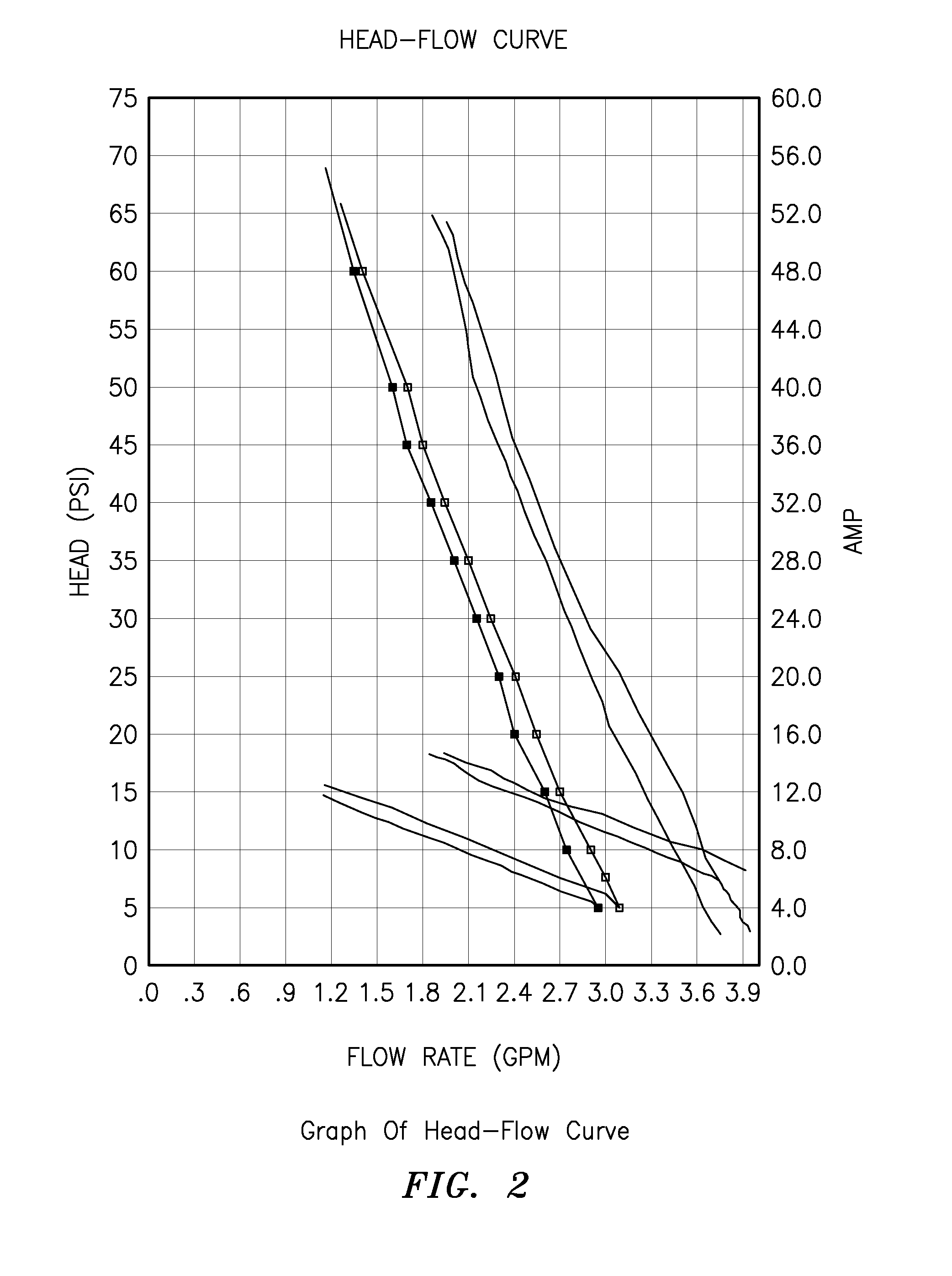
[0027]According to some embodiments of the present invention, the one or more modules 12 may be configured to control the operation of the pump 30 (FIG. 4) based at least partly on a table of characteristics related to voltage and current that is calibrated for each pump, where the characteristics may be determined with the following equation:

I=Vm+C,

where

m=(I1−I2) / (V1−V2),

C=(V1*I2−V2*I1) / (V1−V2),[0028](V1, I1): Low point of curve, and[0029](V2, I2): High point of curve.

The one or more input...


PUM


Abstract

The present invention provides a technique using current sensing to control the pressure at constant level without the direct sensing of the pressure. This technique will help to reduce dependency solely on switch or sensor and their non linearity and other associated problems such as the non-repetitive behavior, being affected by EMI etc. The technique includes using a pump controller featuring one or more modules configured to respond to one or more input signals containing information about current provided from a pump; and configured to provide one or more output signals containing information to control the pump to operate at a substantially constant pressure without the direct sensing of pump pressure. The one or more modules control the operation of the pump based at least partly on a table of characteristics related to voltage and current that is calibrated for each pump.

Description

BACKGROUND OF THE INVENTION[0001]1. Field of the Invention[0002]The present invention relates to a technique for controlling the operation of a pump, including providing a method of controlling the operation of a pump at a constant pressure using motor current as a sensing parameter and motor voltage as a controlling parameter.[0003]More particularly, the present invention relates to a method and apparatus using a pump control to keep an outlet pressure constant based at least partly on sensing motor current and a unique algorithm of tracking the V-I characteristics of a pump.[0004]2. Brief Description of Related Art[0005]Many pumps known in the art include a mechanical pressure switch, or semiconductor hall sensors, or load cells, or any other type of electronic pressure sensing device, that shuts off the pump when certain pressure (i.e., the shut-off pressure) is exceeded. The pressure switch, hall sensor or load cell is typically positioned in physical communication with the flui...

Claims


Application Information

Patent Timeline
Patent Type & Authority Applications(United States)
IPC IPC(8): F04B49/06
CPCF04B49/065F04B2203/0201F04B2205/03
Inventor TRAN, DERRICK THANHDANG, THANG QUOCNAVAL, JR., RUFINOPHILLIPS, DAVID L.
Owner XYLEM IP HLDG
Learn More