Lock-up clutch

a technology of locking clutch and clutch plate, which is applied in the direction of clutches, friction clutches, gearing, etc., can solve the problems of reducing the power transmission efficiency, and achieve the effects of small heat capacity, high surface pressure, and large heat capacity

Inactive Publication Date: 2012-12-27
TOYOTA JIDOSHA KK
View PDF5 Cites 7 Cited by
  • Summary
  • Abstract
  • Description
  • Claims
  • Application Information

AI Technical Summary

Benefits of technology

[0029]The lock-up clutch according to the present invention is provided with the outside friction surfaces to be respectively in frictional contact with the front cover or the lock-up piston each having a large heat capacity, and the inside friction surfaces to be respectively in frictional contact with the torque transmitting plates of a small heat capacity. The outside friction surfaces are narrow in frictional contact area, and thus become high in surface pressure while being easy to dissipate heat, thereby increasing the amount of heat generated per unit area, whereas the inside friction surfaces are wide in frictional contact area, and thus become low in s

Problems solved by technology

The hydraulic power transmission operated always only in the hydraulic powe

Method used


Image

  • Lock-up clutch
  • Lock-up clutch
  • Lock-up clutch

Examples


first embodiment

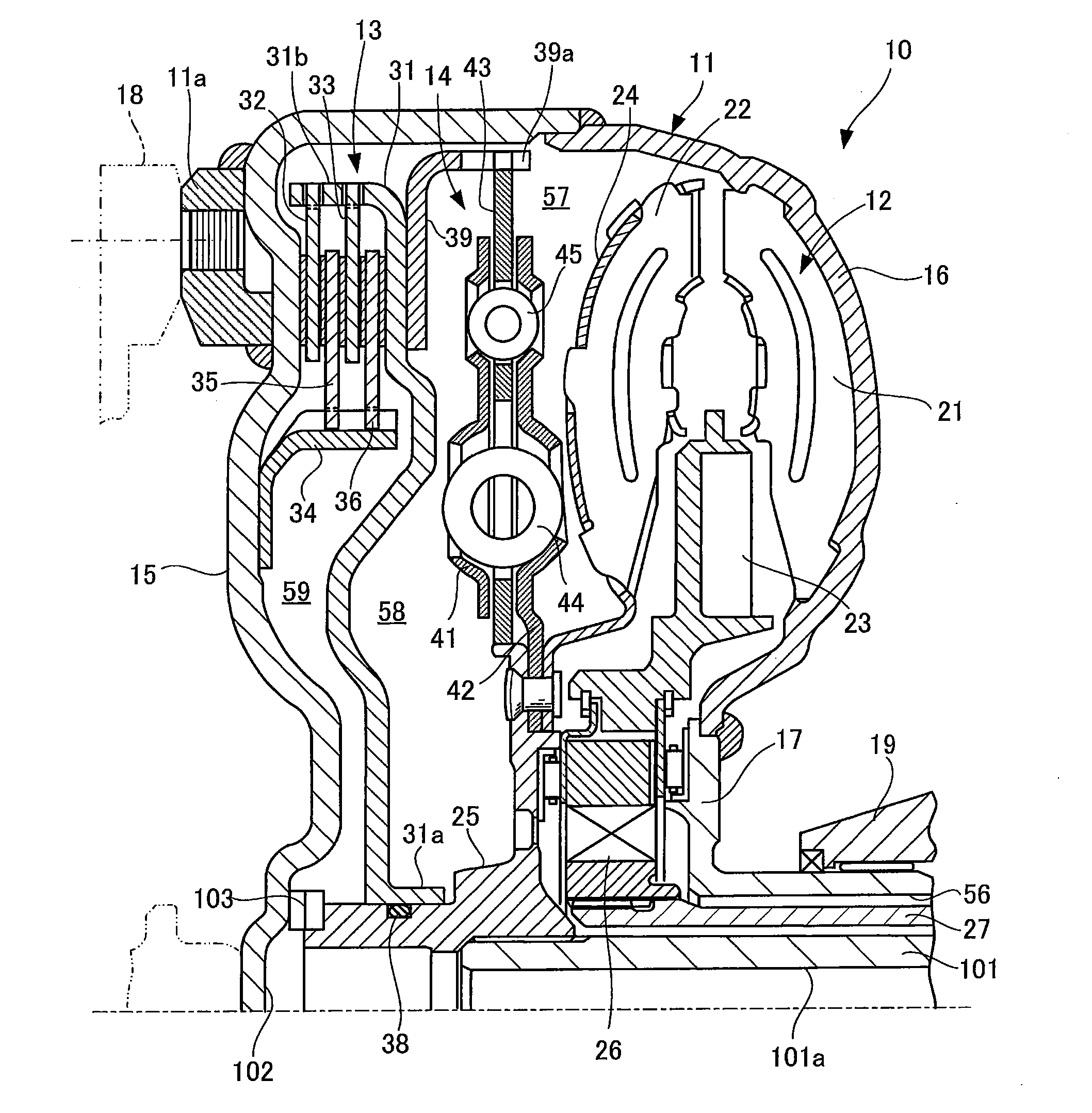
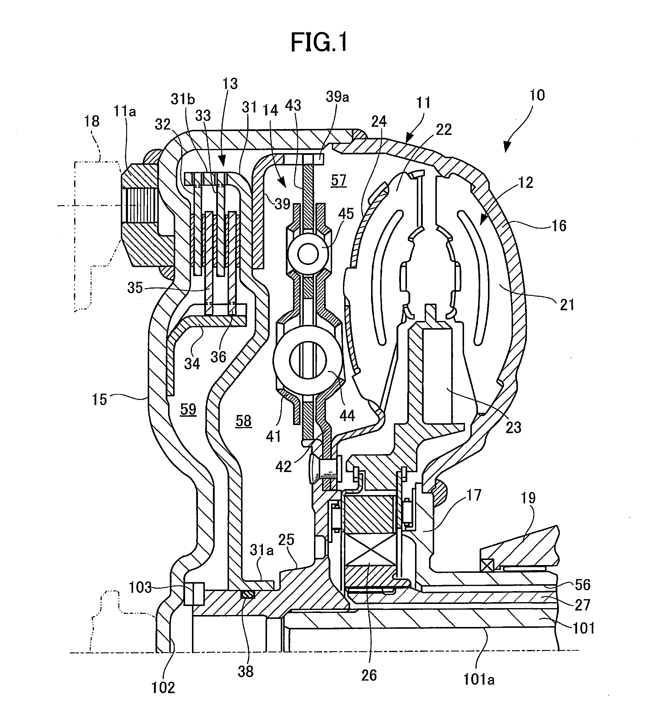
[0037]FIGS. 1 and 2 respectively show a lock-up clutch according to the first embodiment of the present invention, and a hydraulic power transmission provided with a lock-up mechanism assembled with the lock-up clutch. The lock-up clutch according to the present embodiment, and the hydraulic power transmission provided with this lock-up mechanism are to be mounted on a vehicle which is of a front-engine rear drive type. The right side of each of FIGS. 1 and 2 shows a rear side of the vehicle, while the left side of each of FIGS. 1 and 2 shows a front side of the vehicle. The lock-up clutch according to the present invention, and the hydraulic power transmission provided with the lock-up mechanism assembled with the lock-up clutch may, of course, be to be mounted on a vehicle which is of other type than the front-engine rear drive type.

[0038]As shown in FIGS. 1 and 2, the hydraulic power transmission 10 with the lock-up mechanism according to the present embodiment is accommodated in...

second embodiment

[0078]FIGS. 4A and 4B are explanation views respectively showing friction surface shapes of friction materials forming part of the lock-up clutch according to the second embodiment of the present invention. FIG. 4A shows a friction surface shape of an outside friction surface, while FIG. 4B shows a friction surface shape of an inside friction surface.

[0079]The lock-up clutch according to the present embodiment, and the hydraulic power transmission with the lock-up mechanism are substantially the same in construction as the first embodiment previously mentioned except for the shape of the friction surface (groove pattern shape), so that the similar constructions will be explained with the reference numerals and symbols used in FIG. 1, FIG. 2, FIG. 3A and FIG. 3B.

[0080]In the present embodiment as shown in FIG. 4A and FIG. 4B, the first friction material 51 and the second friction material 55 are respectively formed with outside friction surfaces 51f and 55f each having a relatively s...


PUM


Abstract

Disclosed is a lock-up clutch operative to uniform temperatures on a multiple number of friction surfaces, thereby improving accuracy of a lock-up control and to prevent shudders of a vehicle from being generated. The lock-up clutch includes a front cover, a lock-up piston, a plurality of torque transmitting plates, and a plurality of friction materials formed on the torque transmitting plates and having three or more friction surfaces. The friction materials are constituted by a first friction material frictionally contactable with the front cover, a second friction material frictionally contactable with the lock-up piston, and third friction materials frictionally contactable with at least one of the plates. Three or more friction surfaces are constituted by outside friction surfaces formed on the first and second friction materials and each having a small area, and inside friction surfaces formed on the third friction materials and each having a large area.

Description

TECHNICAL FIELD[0001]The present invention relates to a lock-up clutch, and more particularly to a lock-up clutch used as a lock-up mechanism for a hydraulic power transmission such as a torque converter.BACKGROUND ART[0002]In general, an automotive vehicle is provided with a hydraulic power transmission such as a torque converter between an engine and a transmission mechanism forming part of an automatic transmission (hereinafter simply referred to as an automatic transmission). There have so far been developed a wide variety of hydraulic power transmissions one of which is operative to take a power transmitting state in which the hydraulic power can be transmitted from the engine to the input shaft of the automatic transmission (hereinafter simply referred to as a transmission input shaft) while the rotation difference between the engine and the automatic transmission input shaft is being absorbed at the starting time of the engine and other timings. The hydraulic power transmissi...

Claims


Application Information

Patent Timeline
IPC IPC(8): F16D13/52
CPCF16H45/02F16H2045/0205F16H2045/0289F16H2045/0284F16H2045/0226F16D13/648
Inventor YAMASHITA, TOSHIYA
Owner TOYOTA JIDOSHA KK
Why Eureka
Try Eureka