Wireless Power Transmission

a wireless power transmission and wireless technology, applied in the field of wireless power transmission, can solve the problems of large gap between existing technologies and a practical, general-purpose and ubiquitous wireless power transmission system, and the like, and achieve the effects of reducing and increasing the cost of power generation

Active Publication Date: 2012-12-27
BOARD OF RGT THE UNIV OF TEXAS SYST
View PDF28 Cites 512 Cited by
  • Summary
  • Abstract
  • Description
  • Claims
  • Application Information

AI Technical Summary

Benefits of technology

[0011]Example embodiments of the present disclosure are generally directed to a system and method for wireless power transmission, which may have both indoor and outdoor applications. According to one aspect, the system may include one or more charging panels and one or more powered devices configured to selectively operate in a number of modes including a radar mode and power-delivery mode. The charging panel of one aspect may include a pilot analysis circuitry, processor coupled to the pilot analysis circuitry and power transmitter coupled to the processor. The pilot analysis circuitry may be configured to operate in the radar mode to analyze the magnitude and phase of a pilot signal from the powered device. The processor may be configured to

Problems solved by technology

Numerous portable electronic devices such as laptops, cell phones, digital cameras, electric shavers or the like are not “truly portable” as long as they have to be routinely charged by the line power.
Notwithstanding the above and other similar investigations, a large gap still exists between existing technologies and a practical, general-purpose and ubiquitous wireless power transmission system.
During wireless power transmission, power loss is due to many factors, most notably RF-to-direct-current (RF-DC) conversion and RF propagation.
Beamforming may be relatively simple for stationary devices with high-gai

Method used


Image

  • Wireless Power Transmission
  • Wireless Power Transmission
  • Wireless Power Transmission

Examples


Embodiment Construction

[0031]Some embodiments of the present disclosure will now be described more fully hereinafter with reference to the accompanying drawings, in which some, but not all embodiments of the disclosure are shown. Indeed, various embodiments of the disclosure may be embodied in many different forms and should not be construed as limited to the embodiments set forth herein; rather, these example embodiments are provided so that this disclosure will be thorough and complete, and will fully convey the scope of the disclosure to those skilled in the art. Like reference numerals refer to like elements throughout.

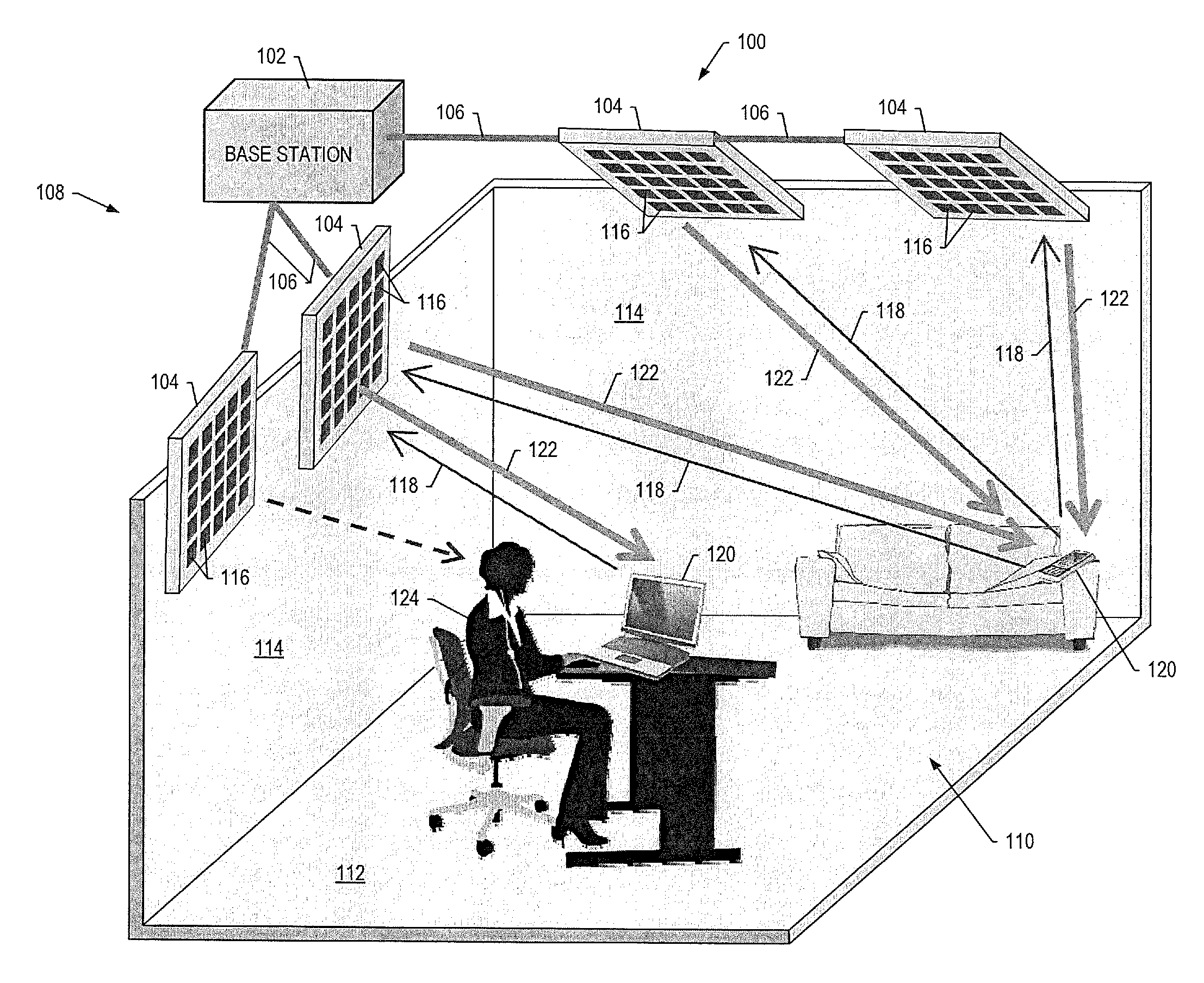
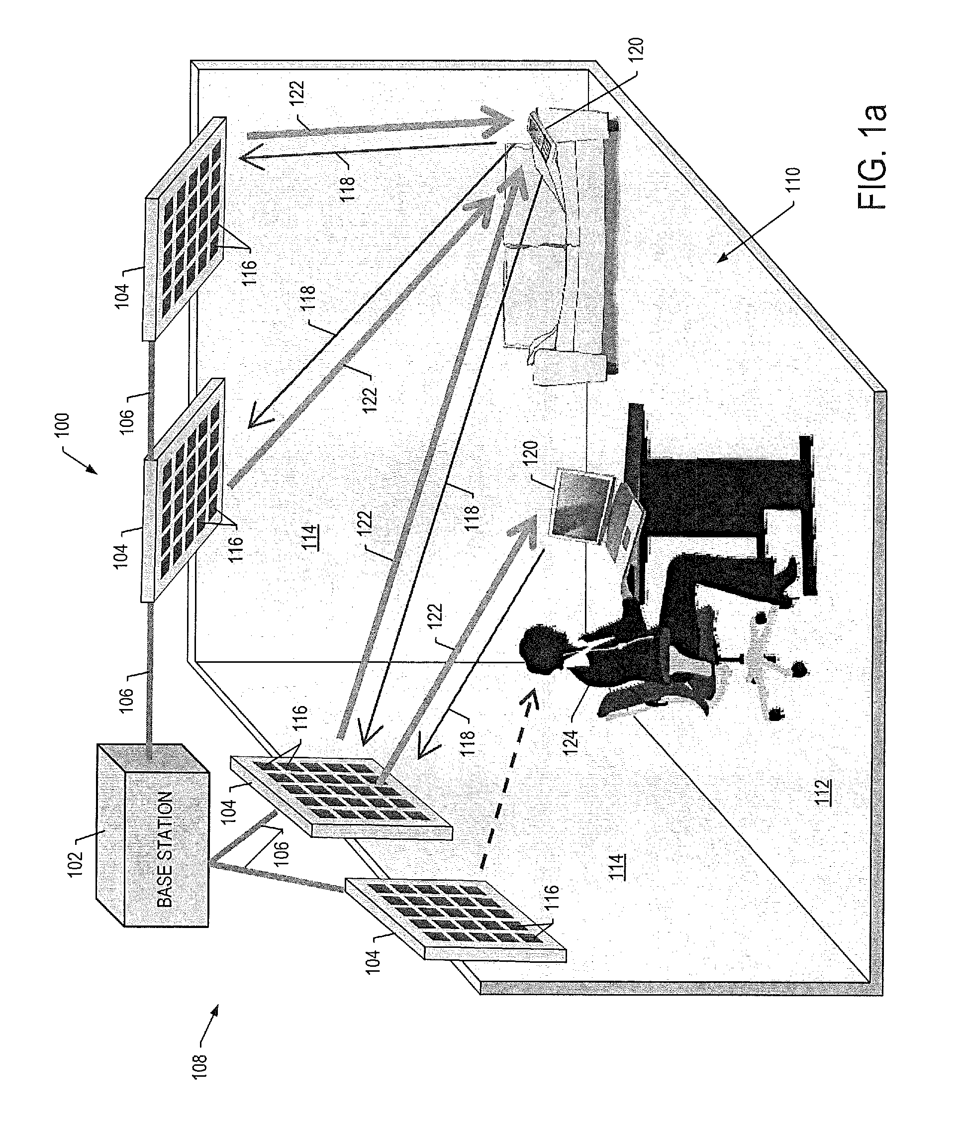
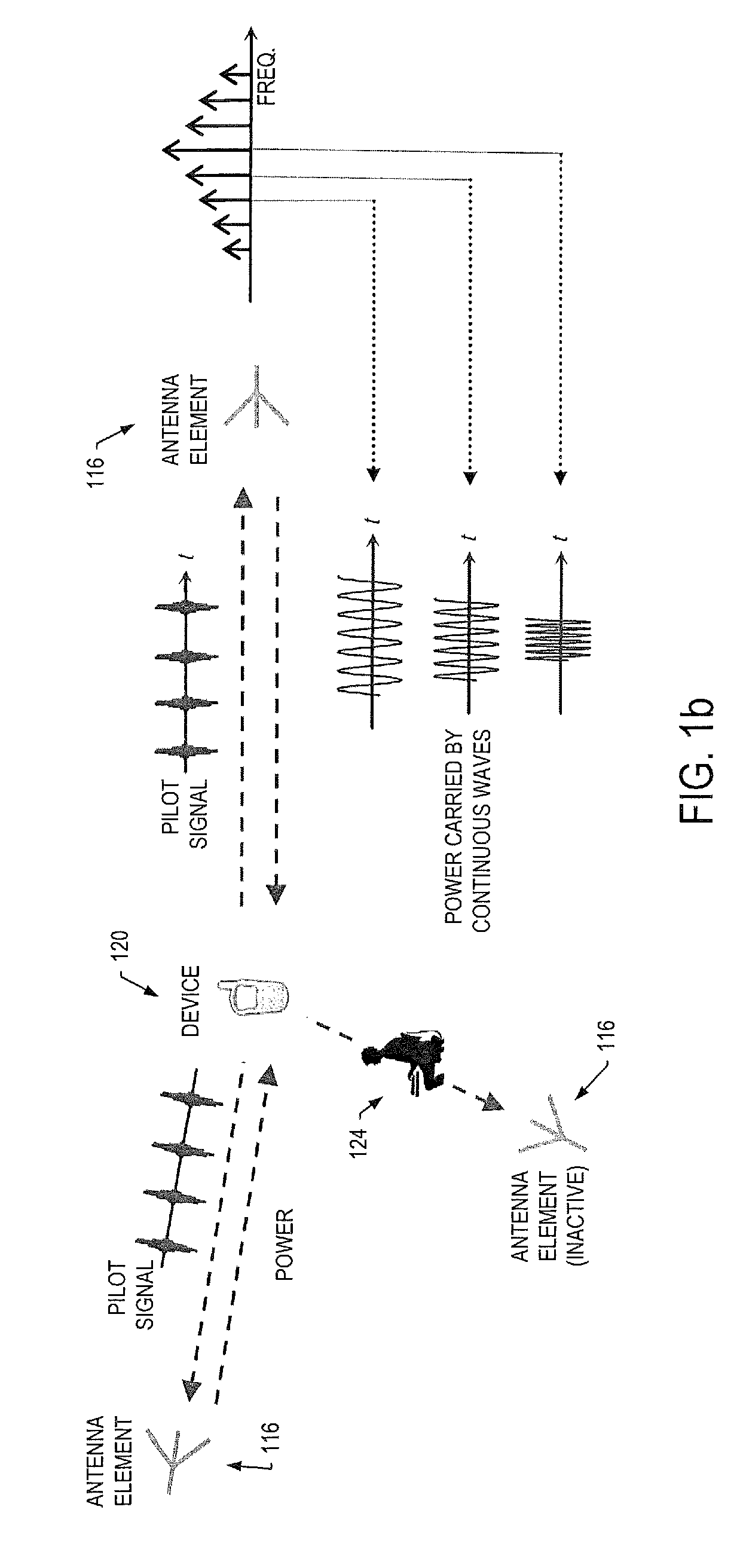
[0032]FIGS. 1a, 1b and 1c illustrate a system 100 for wireless power transmission in accordance with one example embodiment. As shown, the system includes a base station 102 coupled to a plurality of charging panels 104, such as by appropriate wiring 106. In other instances, the base station and charging panels may be referred to as a central station and base stations, respectively. As ...


PUM


Abstract

A system for wireless power transmission may include one or more charging panels and one or more powered devices. The charging panel may include a pilot analysis circuitry, processor and power transmitter. The pilot analysis circuitry may be configured to analyze the magnitude and phase of a pilot signal from the powered device, based on which the processor may be configured to determine a complex conjugate of the pilot signal. And the power transmitter may be configured to cause radiation of a focused wireless power beam to the powered device in accordance with the complex conjugate of the pilot signal and via one or more antenna elements. The charging panel may be one of a plurality of spatially-distributed charging panels each of which includes respective antenna elements that may form an array of antenna elements configured to collaboratively radiate wireless power as a distributed, retro-reflective beamformer.

Description

CROSS-REFERENCE TO RELATED APPLICATION(S)[0001]The present application is related to U.S. Provisional Patent Application No. 61 / 501,331, entitled: A Wireless Charging System and Method, filed on Jun. 27, 2011, the content of which is incorporated herein by reference in its entirety.TECHNOLOGICAL FIELD[0002]The present disclosure relates generally to wireless power transmission and, in particular, to a system and method for wireless power transmission that includes planar, smaller and lighter apparatuses, and that transmits power to devices (e.g., portable devices) and with high power transmission efficiency.BACKGROUND[0003]Numerous portable electronic devices such as laptops, cell phones, digital cameras, electric shavers or the like are not “truly portable” as long as they have to be routinely charged by the line power. A wireless power transmission technique capable of delivering electromagnetic energy to these portable devices without human intervention would make them truly teth...

Claims


Application Information

Patent Timeline
IPC IPC(8): H02J7/00
CPCH02J17/00H01Q9/40H02J7/025G01J1/42H01Q21/061H02J50/20H02J50/005H02J50/60H02J50/10
Inventor LU, MINGYUBILLO, RICHARD E.
Owner BOARD OF RGT THE UNIV OF TEXAS SYST
Why Eureka
Try Eureka