

GPS and MEMS hybrid location-detection architecture
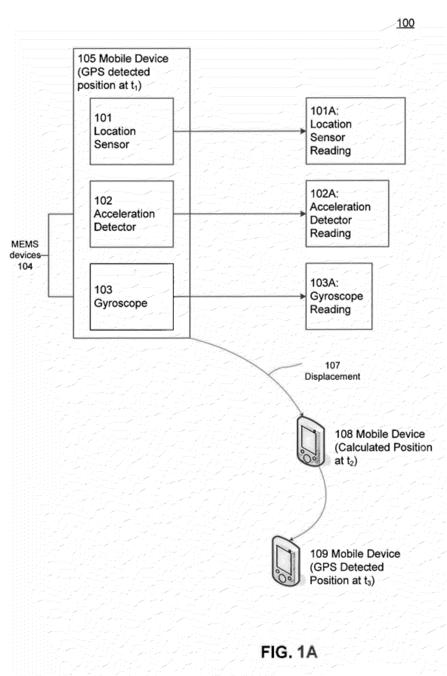
a location detection and hybrid technology, applied in surveying and navigation, instruments, navigation instruments, etc., can solve the problems of consuming substantial energy for receiving and processing gps signals, cell-tower signals may not provide highly accurate or precise information about location, and may not be available gps signals, so as to minimize power consumption
- Summary
- Abstract
- Description
- Claims
- Application Information
AI Technical Summary
Benefits of technology
Problems solved by technology
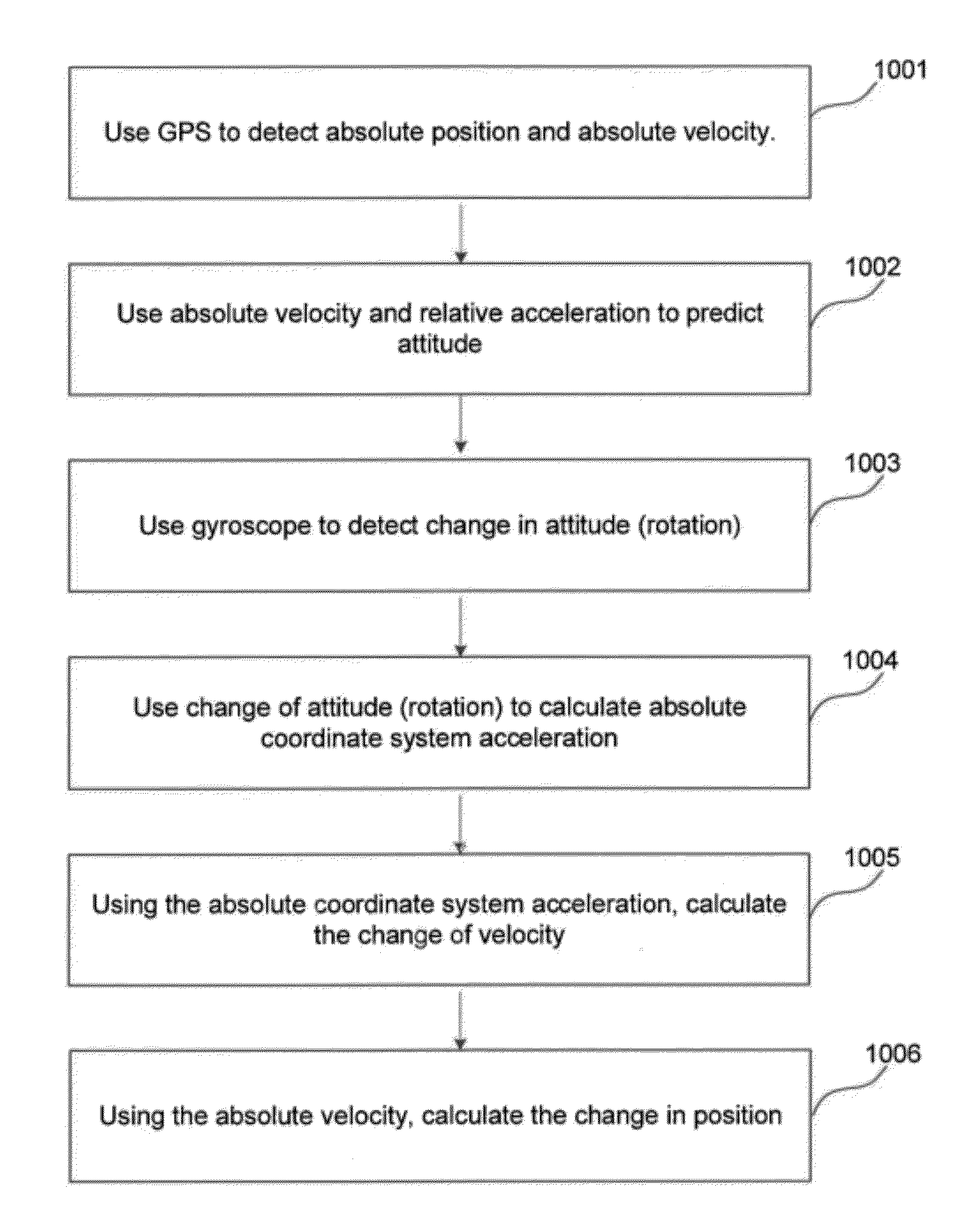
Method used
Image

Examples
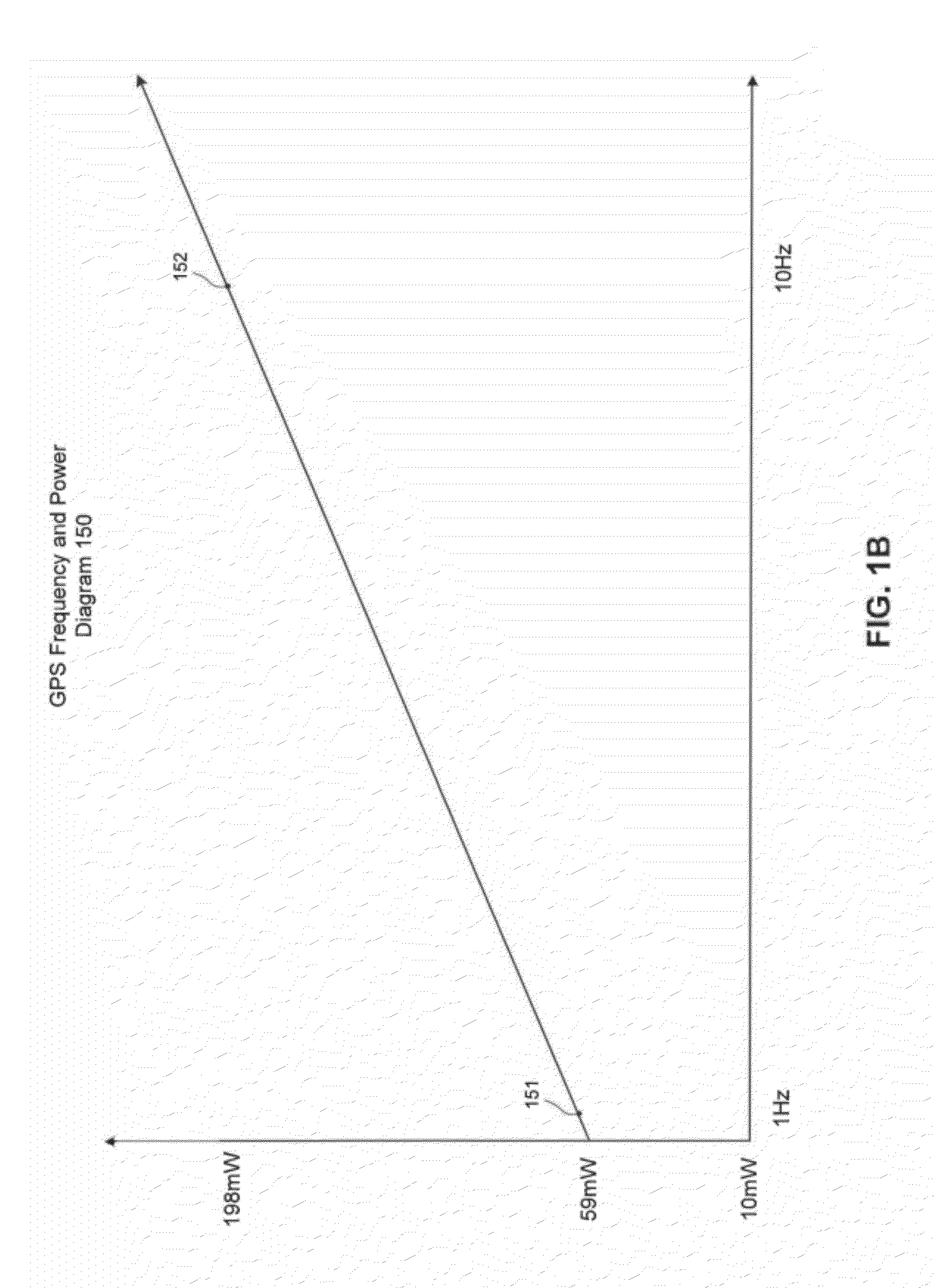
example performance
Parameters and Estimation
[0163]As sample parameters, let
1. DriftGym=10−4 (where 35 degrees drifted after one hour) the rate is:
(35×2π360)2 / 3600=10-4
2. RAR=P(5×10⁻³ g)(1.1 LSB) / (256 LSB / G)
3. dt P(10−2 s) (Acceleration detector 102 frequency)
[0164]For Indoor Usage:
[0165]RL=P(20 m)
[0166]RVA=P(5 cm / s)
[0167]A=0.1 g (walking acceleration)
[0168]V=1 m / s (walking speed)
[0169]So we have
DriftGyro2 / 3T−1 / 3dt1 / 3A4 / 3RVA1 / 3=6×10⁻⁵
RAR=2.5×10⁻³
[0170]PAA=RAR when
DriftGyro2 / 3T−1 / 3dt1 / 3A4 / 3RVA1 / 3>>RAR
[0171]so we can get:
PL=(dtT3 / 4)(RVARAR)1 / 4RL1 / 2
[0172]This indicates, if PL=1 (keep the position in the precision of 1 m), that we only need GPS data once every 100 seconds.
[0173]For Outdoor Usage:
[0174]RL=P(20 m)
[0175]RVA=P(5 cm / s)
[0176]EATT=P(T1 / 210−4)
[0177]A=0.5 g (acceleration in car)
[0178]V=30 m / s (car speed)
[0179]So we now have
DriftGyro2 / 3T−1 / 3dt1 / 3A4 / 3RVA1 / 3=5×10⁻⁴
RAR=2.5×10⁻³
[0180]so we can get:
PL=(dtT3 / 4)(RVARAR)1 / 4RL1 / 2
[0181]This once again indicates, if PL=1 (keep the position in the ...
PUM
 Abstract
Description
Claims
Application Information