Mirror device

a technology of mirrors and mirrors, applied in the field of mirrors, to achieve the effect of large deflection angl

Inactive Publication Date: 2012-12-27
HITACHI MEDIA ELECTORONICS CO LTD
View PDF3 Cites 8 Cited by
  • Summary
  • Abstract
  • Description
  • Claims
  • Application Information

AI Technical Summary

Benefits of technology

[0024]According to the present invention, the first electrostatic actuator and the second electrostatic actuator which are different in properties are combined, and the second movable frame is moved, thus even at a low voltage, the mirror can be driven, and the movable frame is moved until the mirror makes contact with the insulators formed on the inclined electrodes, thereby a large deflection angle can be repeatedly obtained.

Problems solved by technology

However, regarding the vertical direction ±6° at 60 Hz drive, the resonance frequency cannot be lowered to 60 Hz from the viewpoint of the disturbance resistance as a display device, so it is necessary to obtain a large deflection angle by the dissonance drive.

Method used


Image

  • Mirror device
  • Mirror device
  • Mirror device

Examples


embodiment 1

[0044]Regarding this embodiment, the case where it is used for image drawing will be explained as an embodiment by referring to FIGS. 3 to 9.

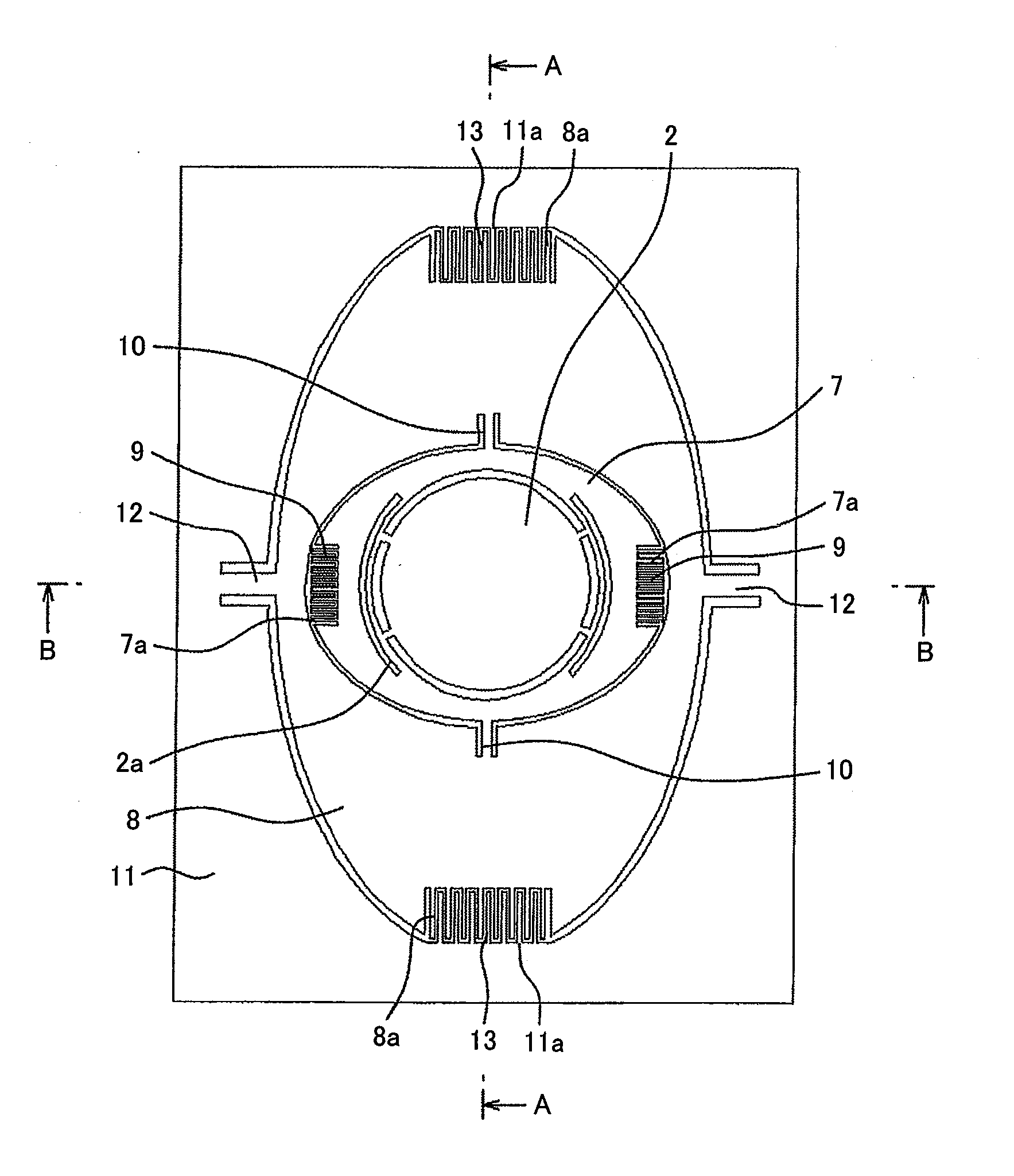
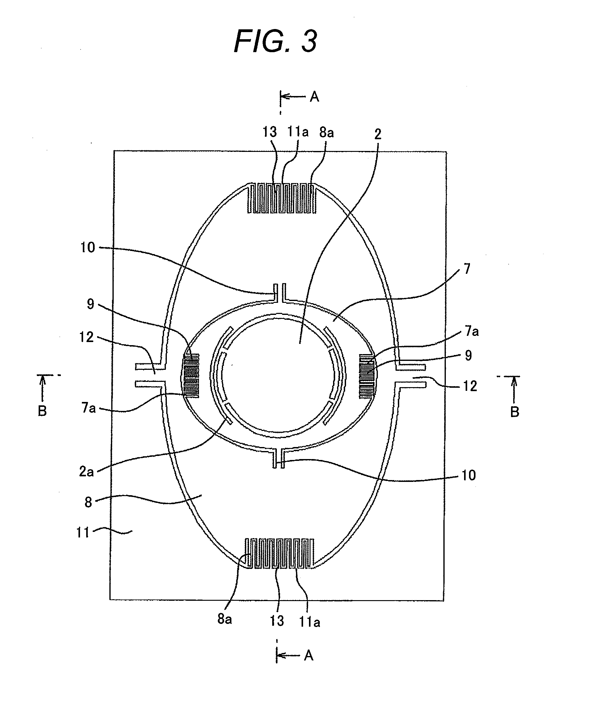
[0045]FIG. 3 is a front view of the mirror device relating to the first embodiment of the present invention.

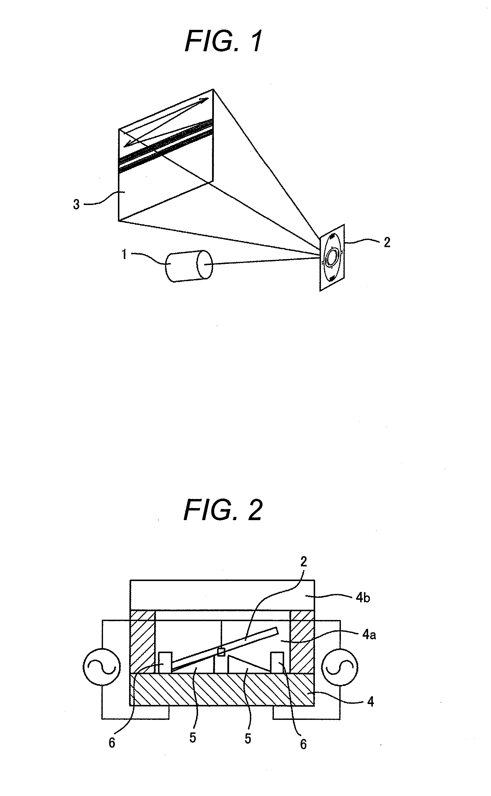
[0046]FIG. 4 is a cross sectional view of the line A-A shown in FIG. 3.

[0047]FIG. 5 is a cross sectional view of the line B-B shown in FIG. 3.

[0048]In FIG. 3, the mirror 2 for reflecting light is connected to a first movable frame 7 via a distortion separation portion 2a and is fixed in the same plane. The distortion separation portion 2a prevents the mirror 2 from deforming due to a temperature change or force applied at the time of mounting.

[0049]The first movable frame 7 is connected to a second movable frame 8 with torsion beams 10 symmetrically arranged on the axial line passing the center of the mirror. Further, the first movable frame 7 rotates around the axis composed of the torsion beams 10 by comb-tooth electrode type electrosta...

embodiment 2

[0072]FIG. 7 is a front view of the biaxial electrostatic drive mirror device relating to Embodiment 2 of the present invention.

[0073]In FIG. 7, the mirror 2 for reflecting light is connected to the first movable frame 7 via the distortion separation portion 2a and is fixed in the same plane. The distortion separation structure 2a prevents the mirror 2 from deforming due to a temperature change or force applied at the time of mounting.

[0074]The first movable frame 7 is connected to the second movable frame 8 with the torsion beams 10 symmetrically arranged on the axial line passing the center of the mirror and rotates around the axis composed of the torsion beams 10 by the comb-tooth electrode type electrostatic actuators 9 formed at the ends in the rotational direction. If the first movable frame 7 is used to draw an image in the horizontal direction, the drive frequency thereof is high such as 10 kHz or higher.

[0075]When the resonance frequency is high like this, the comb-tooth el...

embodiment 3

[0082]FIG. 8 is a front view of the biaxial electrostatic drive mirror device relating to Embodiment 3 of the present invention.

[0083]In FIG. 8, the mirror 2 for reflecting light is connected to the first movable frame 7 via the distortion separation portion 2a and is fixed in the same plane. The distortion separation portion 2a prevents the mirror 2 from deforming due to a temperature change or force applied at the time of mounting. The first movable frame 7 is connected to the second movable frame 8 with the torsion beams 10 symmetrically arranged on the axial line passing the center of the mirror 2 and rotates around the axis composed of the torsion beams 10 by the comb-tooth electrode type electrostatic actuators 9 formed at the ends in the rotational direction. If the first movable frame 7 is used to draw an image in the horizontal direction, the drive frequency thereof is high such as 10 kHz or higher.

[0084]When the resonance frequency is high like this, the comb-tooth electro...


PUM


Abstract

In a biaxial mirror device where beams for connecting a first movable frame to a second movable frame and the second movable frame to a fixed frame pass a center of the mirror along an axis, an actuator for moving the second movable frame is composed of two first and second actuators and in a state that rotational angles of the movable frames are zero, the first actuator permits the second movable frame to start rotation and when it reaches a specific rotational angle, the second actuator permits the second movable frame to rotate, thus a large deflection angle is obtained even by the dissonance drive.

Description

CLAIM OF PRIORITY[0001]The present application claims priority from Japanese patent application serial No. 2011-138131, filed on Jun. 22, 2011, the content of which is hereby incorporated by reference into this application.FIELD OF THE INVENTION[0002]The present invention relates to a mirror device loaded in an image projector such as a microminiature projector for projecting an image.BACKGROUND OF THE INVENTION[0003]Generally, a projector projects an image on a large screen in a movie theater or a conference room and is used as equipment for permitting many people to share information at a time.[0004]However, recently, the commercialization of a microminiature projector capable of being loaded in a portable telephone such as a pico-projector using an LED (light emitting diode) or an LD (laser diode) is in progress.[0005]The pico-projector is recently noted as a device capable of projecting an image in any favorite place and the Nikkei Electronics for 2010, August to September predi...

Claims


Application Information

Patent Timeline
Patent Type & Authority Applications(United States)
IPC IPC(8): G02B26/10
CPCG02B26/0841H04N9/3129G02B26/101
Inventor KOIDE, AKIRAHOSAKA, NORIO
Owner HITACHI MEDIA ELECTORONICS CO LTD
Why Eureka
Try Eureka