

Optical image capturing assembly
a technology of optical image and assembly, applied in the field of compact, can solve the problems of inability to produce high-quality images, insufficient degree of freedom in setting system parameters, and the length of the total optical track of the lens structur
- Summary
- Abstract
- Description
- Claims
- Application Information
AI Technical Summary
Benefits of technology
Problems solved by technology
Method used
Image

Examples
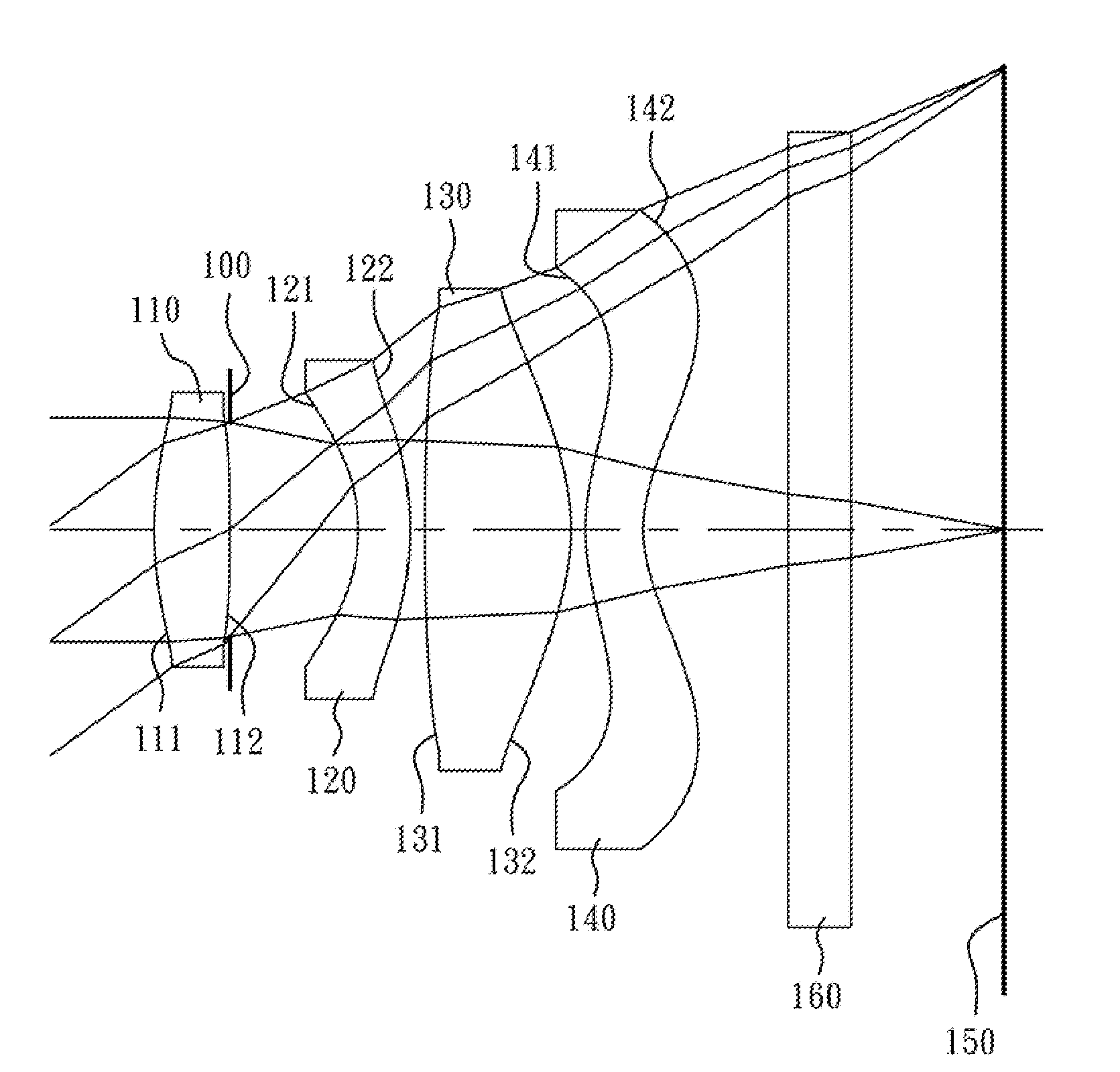
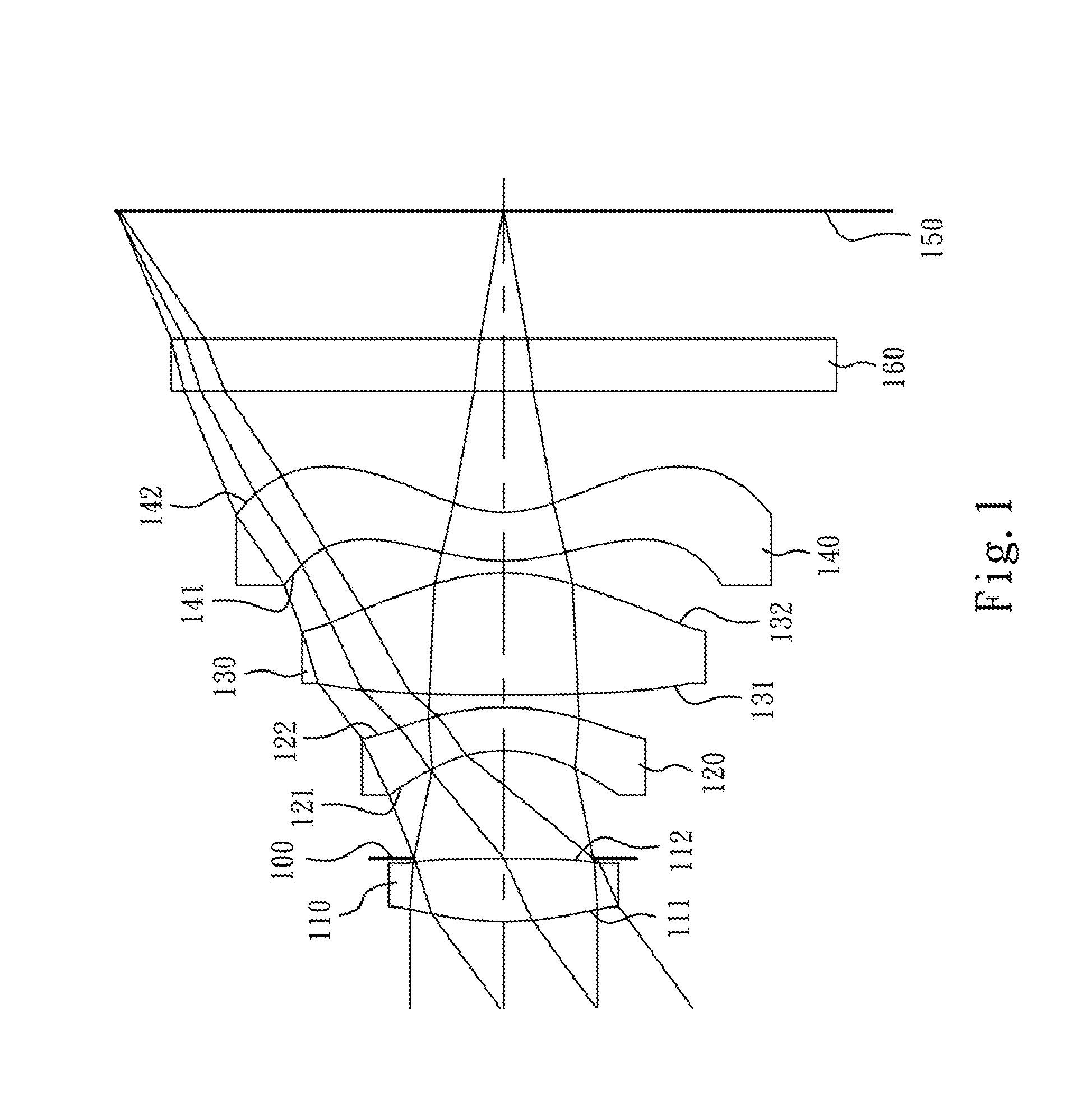
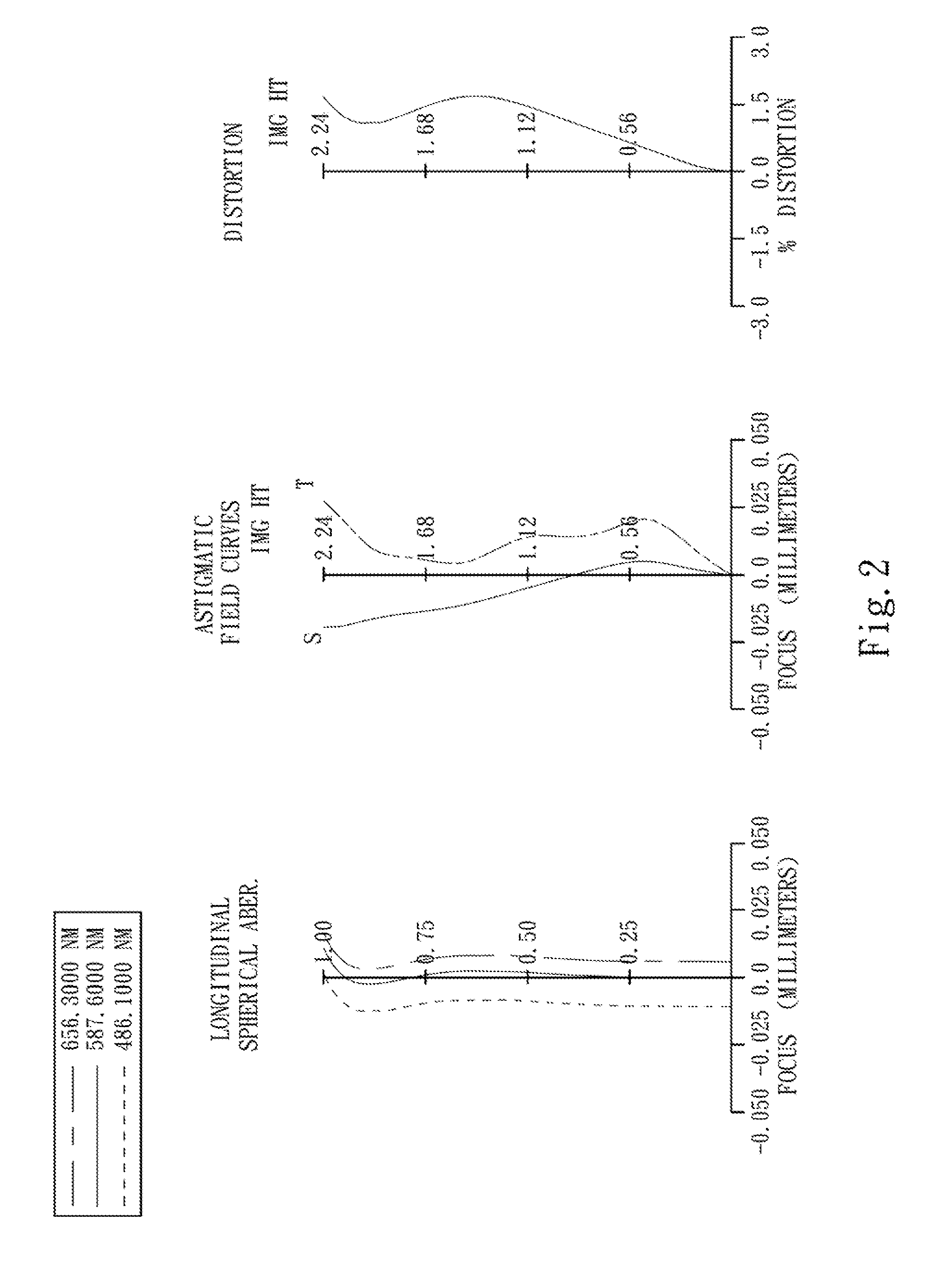
first embodiment
[0066]The equation of the aspheric surface profiles of the aforementioned lens elements of the first embodiment is expressed as follows:
X(Y)=(Y2 / R) / (1+sqrt(1-(1+k)×(Y / R)2))+∑i(Ai)×(Y′)
[0067]where:
[0068]X is the height of a point on the aspheric surface spaced at a distance Y from the optical axis relative to the tangential plane at the aspheric surface vertex;
[0069]Y is the distance from the point on the curve of the aspheric surface to the optical axis;
[0070]R is the curvature radius of the lens elements;
[0071]k is the conic coefficient; and
[0072]Ai is the i-th aspheric coefficient.
[0073]In the optical image capturing assembly according to the first embodiment, when a focal length of the optical image capturing assembly is f, an f-number of the optical image capturing assembly is Fno, a half of the maximal field of view is HFOV, and a maximal field of view of the optical image capturing assembly is FOV, these parameters have the following values:
[0074]f=3.03 mm;
[0075]Fno=2.80;
[0076...
second embodiment
[0094]The detailed optical data of the second embodiment are shown in Table 3 and the aspheric surface data are shown in Table 4 below.
TABLE 32nd Embodimentf = 2.80 mm, Fno = 2.60, HFOV = 38.0 deg.FocalSurface #Curvature RadiusThicknessMaterialIndexAbbe #length0ObjectPlanoInfinity1Lens 1 1.434520 (ASP)0.408Plastic1.54455.92.90214.373200 (ASP)0.0403Ape.Plano0.549Stop4Lens 2−0.774350 (ASP)0.250Plastic1.63423.8−3.545−1.330710 (ASP)0.0506Lens 3 6.831500 (ASP)0.701Plastic1.54455.91.747−1.060510 (ASP)0.0508Lens 4 1.322630 (ASP)0.250Plastic1.63423.8−2.749 0.695700 (ASP)0.70010IR-filterPlano0.300Glass1.51664.1—11Plano0.50912ImagePlano—Note:Reference wavelength (d-line) is 587.6 nm.
TABLE 4Aspheric CoefficientsSurface #1245k =−8.75137E−01−1.00000E+00−8.49115E−018.36011E−01A4 =−3.09101E−03−1.30466E−01−2.42867E−01−2.87889E−01 A6 =−1.01472E−01−1.09584E−01 4.32416E−015.90500E−01A8 =−2.92796E−02−3.80604E−01−1.52982E+002.01908E−01A10 = 5.07425E−02−5.98388E−01 1.26593E+011.63812E−01A12 =−1.81319...
third embodiment
[0103]The detailed optical data of the third embodiment are shown in Table 5 and the aspheric surface data are shown in Table 6 below.
TABLE 53rd Embodimentf = 2.77 mm, Fno = 2.70, HFOV = 38.0 deg.SurfaceFocal#Curvature RadiusThicknessMaterialIndexAbbe #length0ObjectPlanoInfinity1Ape.Plano−0.034 Stop2Lens 1 1.433490 (ASP)0.416Plastic1.54455.92.583−66.967400 (ASP) 0.4554Lens 2−1.107850 (ASP)0.266Plastic1.65021.4−3.535−2.343510 (ASP)0.1886Lens 3 9.762800 (ASP)0.607Plastic1.54455.91.747−1.024250 (ASP)0.0708Lens 4 1.455310 (ASP)0.300Plastic1.54455.9−2.219 0.610670 (ASP)0.70010IR-filterPlano0.300Glass1.51664.1—11Plano0.30212ImagePlano—Note:Reference wavelength (d-line) is 587.6 nm.
TABLE 6Aspheric CoefficientsSurface #2345k =−1.41126E+00−1.00000E+00−1.41060E−012.48501E+00A4 =−1.15519E−02−2.13068E−01−3.52492E−01−3.32049E−01 A6 =−1.72412E−01−1.97363E−01 3.03350E−015.29170E−01A8 = 1.79664E−02−7.10262E−01 1.29379E+002.48759E−01A10 =−1.23058E+00 1.02415E+00 4.04225E−015.69348E−02A12 = 6...
PUM
 Abstract
Description
Claims
Application Information