Method and system for engine control

a technology of engine control and engine start, applied in the direction of engine starters, machines/engines, instruments, etc., can solve the problems of degrading adding component costs to the vehicle system, and reducing the quality of engine restart, so as to reduce noise, reduce exhaust emissions, and save fuel

Active Publication Date: 2012-12-27
FORD GLOBAL TECH LLC
View PDF14 Cites 40 Cited by
  • Summary
  • Abstract
  • Description
  • Claims
  • Application Information

AI Technical Summary

Benefits of technology

[0002]Vehicles have been developed to perform an engine idle-stop when idle-stop conditions are met and then automatically restart the engine when restart conditions are met. The engine may be restarted with assistance from a starter motor, for example. Such idle-stop systems enable fuel savings, reduction in exhaust emissions, reduction in noise, and the like. Vehicle systems may include a parking brake, in addition to wheel brakes, to assist in keeping the vehicle stationary when parked, in particular, when parked on an incline. During an engine restart on an incline, the engagement of the parking brake may be coordinated with the cranking of the engine to prevent the vehicle from rolling backwards.

Problems solved by technology

However, the inventors herein have identified a potential issue with such an approach.
The need for a compressor to provide the compressed air adds component costs to the vehicle system.
However, since operation of the electric brake requires a current to be drawn, the electric brake and the starter motor cannot be operated simultaneously.
As such, the electrical supply of the vehicle (e.g., battery) may not be able to provide sufficient current to operate both the starter motor and the brake, leading to degraded engine restart quality and degraded brake assistance.
For example, when the restart request is received after the electric brake request, current supplied to the starter may be limited.
Alternatively, if the restart request is received before the electric brake request, the current supplied to the electric brake may be limited.

Method used


Image

  • Method and system for engine control
  • Method and system for engine control
  • Method and system for engine control

Examples


Embodiment Construction

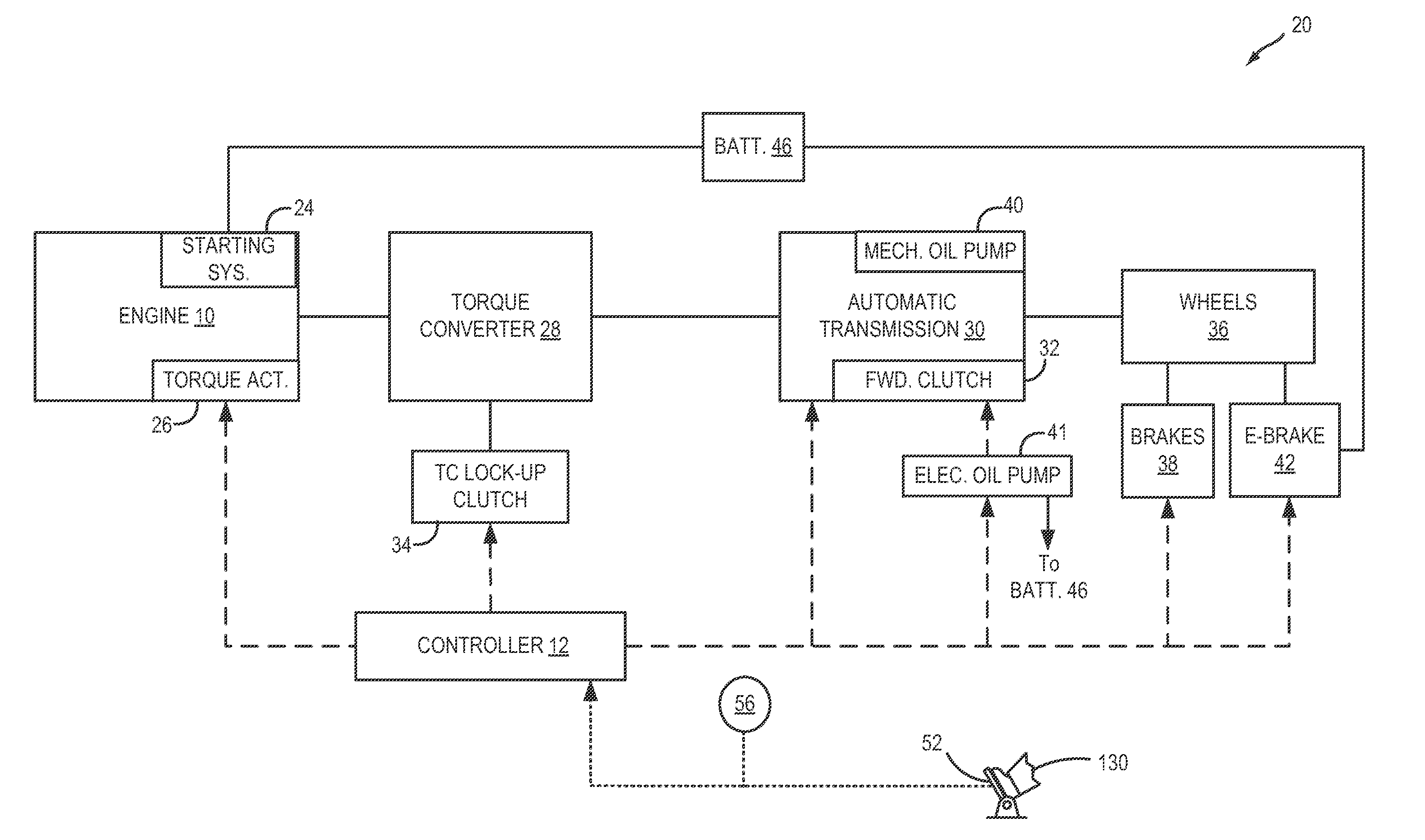
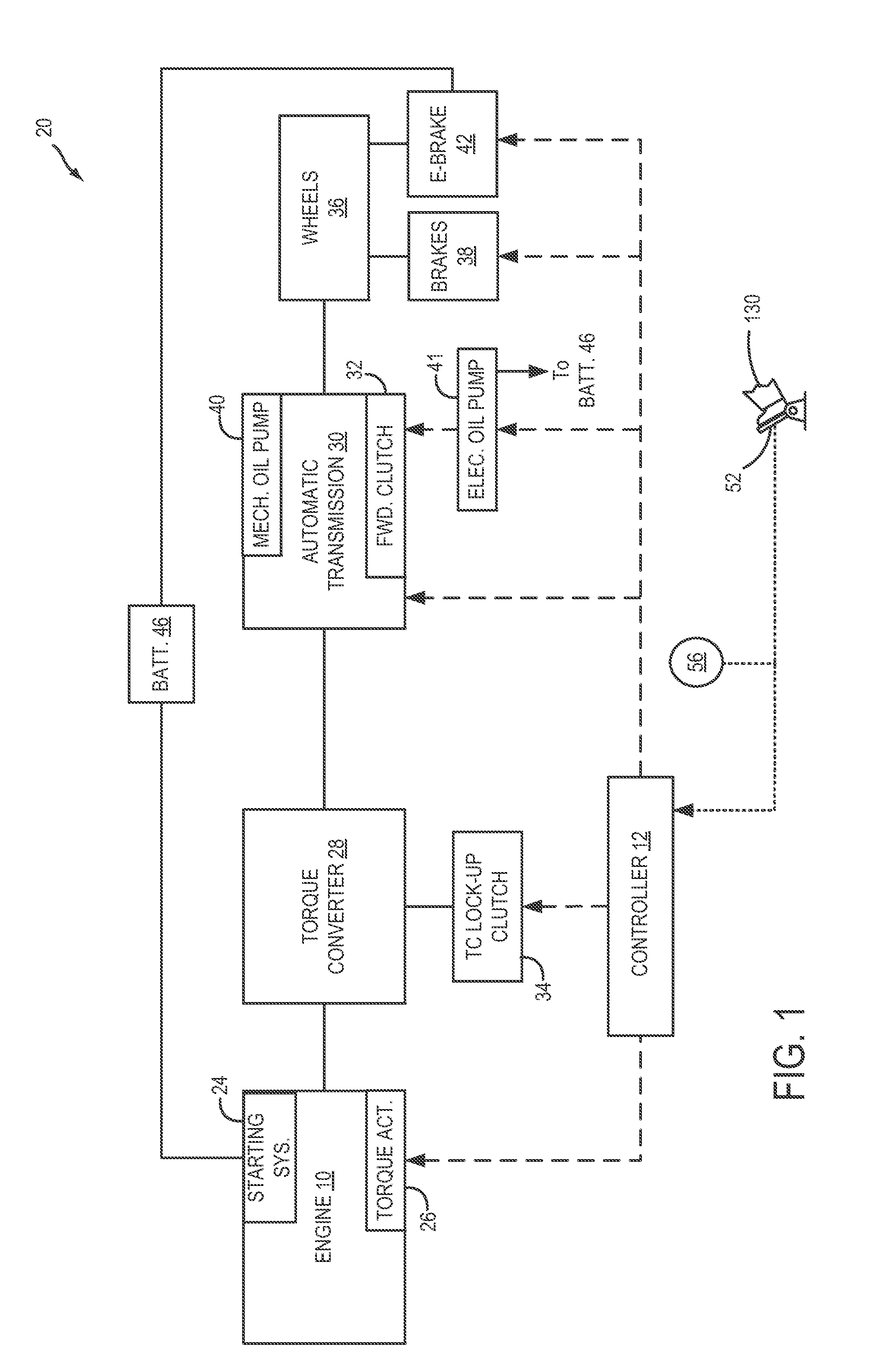
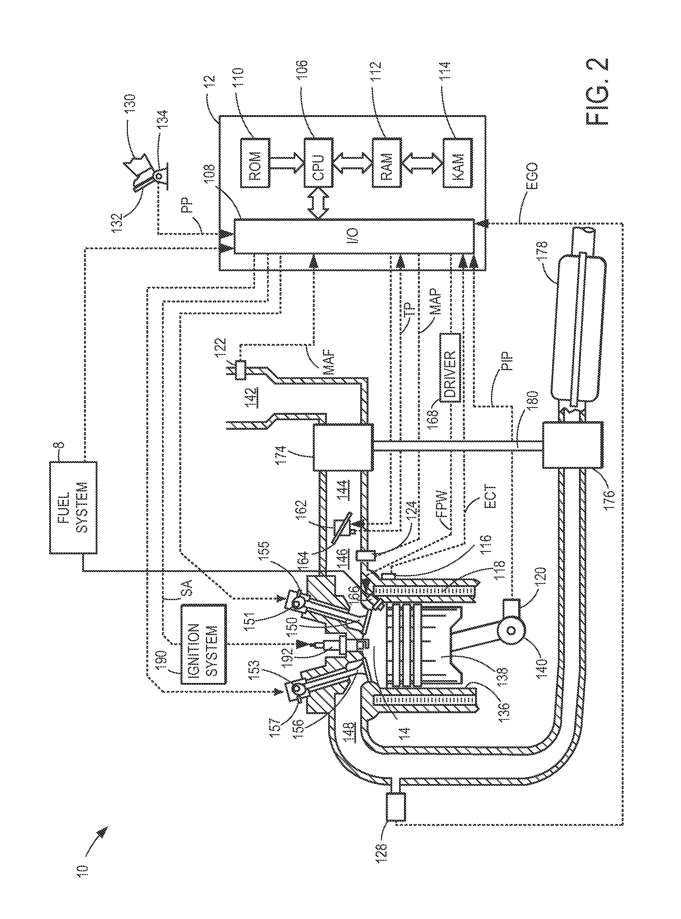
[0015]The following description relates to a vehicle engine system that is selectively deactivatable in response to idle-stop conditions (such as the engine system of FIGS. 1-2). The engine system may be coupled to a transmission and wheel brakes, and further coupled to an electric brake. During idle-stop conditions, based on a vehicle speed at which an electric brake request is received, current may be directed to the electric brake to hold the vehicle stationary. During restart conditions, current may be directed to a starter motor and the electric brake sequentially, the order of directing current based at least on an order in which the requests are received, and further based on an engine speed at the time of the requests. An engine controller may be configured to perform a control routine, such as the routine of FIG. 3, to shut-down the engine in response to idle-stop conditions with the transmission tied to a case of the transmission. The engine controller may be further confi...


PUM


Abstract

Systems and methods are provided for restarting an engine that can be selectively deactivated during idle-stop conditions. In one embodiment, current is directed to a starter motor and an electric brake sequentially by limiting the current supplied to one while current is supplied to the other, an order of delivering the current based on a timing of a restart request relative to an electric brake request, as well as vehicle operating conditions at the time the requests were received. By coordinating the operation of a starter motor with the operation of an electric brake, overloading of the engine system's electrical supply can be reduced.

Description

FIELD [0001]The present application relates to methods and systems for controlling an engine shut-down responsive to idle-stop conditions, and a subsequent engine restart from the idle-stop.BACKGROUND AND SUMMARY[0002]Vehicles have been developed to perform an engine idle-stop when idle-stop conditions are met and then automatically restart the engine when restart conditions are met. The engine may be restarted with assistance from a starter motor, for example. Such idle-stop systems enable fuel savings, reduction in exhaust emissions, reduction in noise, and the like. Vehicle systems may include a parking brake, in addition to wheel brakes, to assist in keeping the vehicle stationary when parked, in particular, when parked on an incline. During an engine restart on an incline, the engagement of the parking brake may be coordinated with the cranking of the engine to prevent the vehicle from rolling backwards.[0003]One example of such coordination is illustrated by Hiyoshi et al. in ...

Claims


Application Information

Patent Timeline
Patent Type & Authority Applications(United States)
IPC IPC(8): B60T7/12B60W30/18B60W10/18
CPCB60W10/06B60W10/115B60W10/182B60W10/30B60W30/18018Y10T477/813B60W2520/10B60W2540/12B60W2710/305B60Y2300/90Y10T477/644B60W2510/0638F02N11/0833F02N2200/0803F02N2250/02Y02T10/40
Inventor GIBSON, ALEX O'CONNORGRIFFIN, CHAD EVERETTENEDOREZOV, FELIX
Owner FORD GLOBAL TECH LLC
Why Eureka
Try Eureka