Metal cored welding method and system

a metal core and welding method technology, applied in the field of welding techniques, can solve the problems of inert shielding gas, relatively expensive, and common divisions between thes

Inactive Publication Date: 2013-01-03
ILLINOIS TOOL WORKS INC
View PDF6 Cites 21 Cited by
  • Summary
  • Abstract
  • Description
  • Claims
  • Application Information

AI Technical Summary

Problems solved by technology

However, further divisions between these are common, particularly in processes that consume an electrode to add filler metal to the weld.
For example, solid wire, while less expensive than the other types, is typically used with inert shielding gases, which can be relatively expensive.
Flux cored wires may not require separate shielding gas feeds, but are more expensive than solid wires.
Although metal cored wires offer distinct advantages over the other electrode types, its adoption has not been as widespread as solid wires.

Method used


Image

  • Metal cored welding method and system
  • Metal cored welding method and system
  • Metal cored welding method and system

Examples


Embodiment Construction

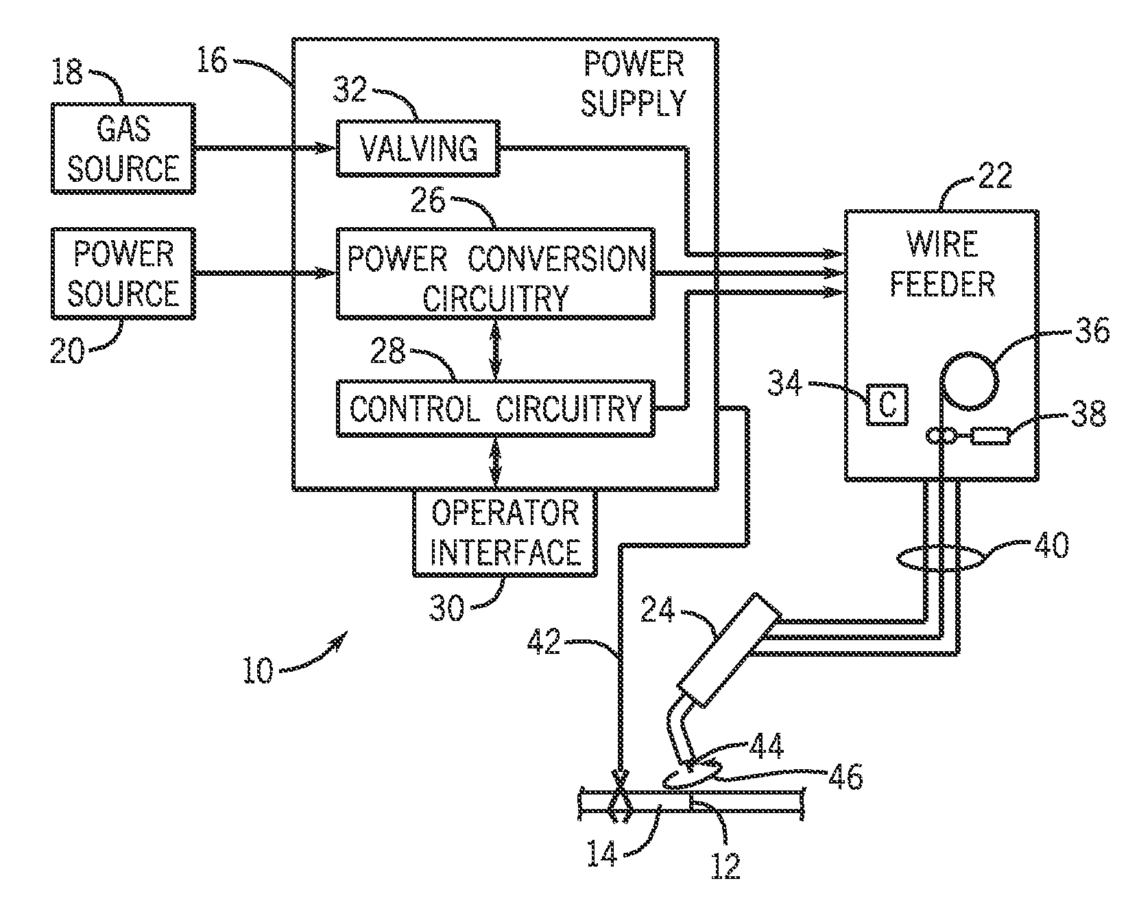
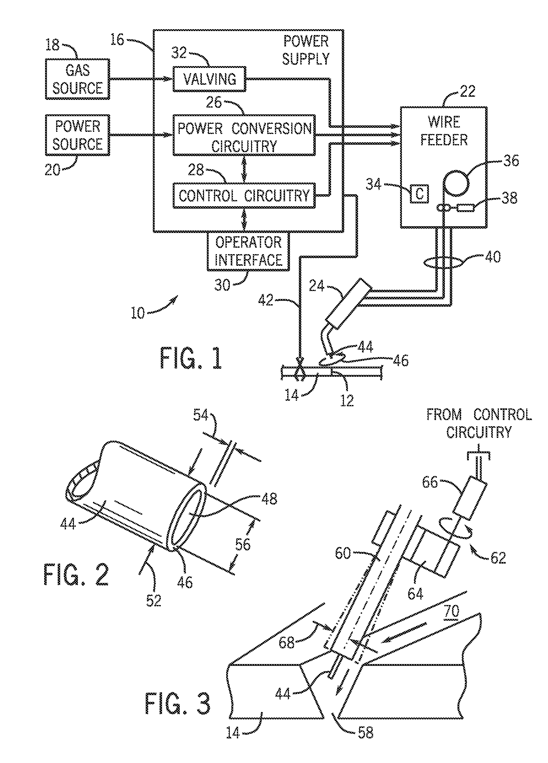
[0016]FIG. 1 illustrates an exemplary welding system 10 utilizing movement of a metal cored welding wire electrode. The system 10 is designed to produce a weld 12 and a workpiece 14. The weld may be of any type and oriented in any desired manner, including butt welds, lap welds, angled welds, out-of-position welds, and so forth. The system includes a power supply 16 that will typically be coupled to a gas source 18 and to a power source 20, such as the power grid. Other power sources may, of course, be utilized including generators, engine-driven power packs, and so forth. A wire feeder 22 is coupled to the power source 20 and supplies metal cored welding wire to a welding gun 24. As described in detail below, the metal cored welding wire is forced to move during creation of a weld bead, causing movement of an arc between a sheath of the metal cored welding wire and the workpiece.

[0017]In the illustrated embodiment, the power supply 16 will include power conversion circuitry 26 coup...


PUM

PropertyMeasurementUnit
diametersaaaaaaaaaa
diametersaaaaaaaaaa
lengthaaaaaaaaaa

Abstract

Methods and systems are disclosed for utilizing metal cored welding wire electrodes with forced movement of the electrode and arc. The electrode may be moved by a motion control assembly in a welding torch. The arc is established only between the sheath of the metal cored welding wire and the workpiece (or weld puddle), providing a unique transfer mode for enhanced deposition, travel speeds, and other weld and process characteristics.

Description

BACKGROUND[0001]The invention relates generally to welding techniques, and more particularly to improved processes for utilizing metal cored welding wire electrodes for enhanced performance, particularly in automated welding applications.[0002]A range of techniques have been developed for joining workpieces by welding operations. These include diverse processes and materials, with most modern processes involving arcs developed between a consumable or non-consumable electrode and the workpieces. The processes are often grouped in such categories as constant current processes, constant voltage processes, pulsed processes, and so forth. However, further divisions between these are common, particularly in processes that consume an electrode to add filler metal to the weld. In virtually all such cases, the process selected is highly linked to the filler material and its form, with certain processes exclusively utilizing a particular type of electrode. For example, certain types of metal ...

Claims


Application Information

Patent Timeline
Patent Type & Authority Applications(United States)
IPC IPC(8): B23K9/12
CPCB23K9/073B23K9/09B23K9/0216B23K9/126B23K9/173B23K9/125
Inventor PAGANO, KEVINSUMMERS, KEVIN
Owner ILLINOIS TOOL WORKS INC
Why Eureka
Try Eureka