Radiation sensing thermoplastic composite panels

a thermoplastic composite panel and radiation sensing technology, applied in the field of scintillation materials, can solve the problems of reducing image resolution, reducing conversion efficiency, and reducing image resolution

Active Publication Date: 2013-01-03
CARESTREAM DENTAL TECH TOPCO LTD
View PDF9 Cites 18 Cited by
  • Summary
  • Abstract
  • Description
  • Claims
  • Application Information

AI Technical Summary

Problems solved by technology

When a continuous, homogeneous scintillation layer is used, lateral propagation of scintillation light is known to reduce image resolution.
Detection by more than one photodetector usually results in reduced image resolution.
However, the thinner the scintillation layer, the lower the conversion efficiency since there is less scintillating material for a source radiation photon to stimulate.
However, this potential is difficult to realize in practical applications due to the mechanical and environmental fragility of CsI-based materials.
CsI:Tl structures are also mechanically fragile, requiring special handling procedures during and after manufacture such as complete enclosure in shock resistant containers.
As a result, production (and end product) costs are quite high in applications that have successfully realized the image quality benefit of thallium doped cesium iodide scintillation panels.
However, while the most transparent scintillator would be a single crystal, single crystal scintillator panels have not yet been constructed with practically useful dimensions and sufficient X-ray absorptivity for radiographic applications.
Another option for increasing transparency is to disperse particulate scintillators in a polymeric matrix having a refractive index identical or closely similar to that of the scintillator; however, this approach requires a high loading of scintillator particles in the polymeric matrix, which to date has not yet been successfully achieved with practically useful dimensions and sufficiently high scintillator particulate loads.

Method used


Image

  • Radiation sensing thermoplastic composite panels
  • Radiation sensing thermoplastic composite panels
  • Radiation sensing thermoplastic composite panels

Examples


examples

Composite Thermoplastic Particle Production

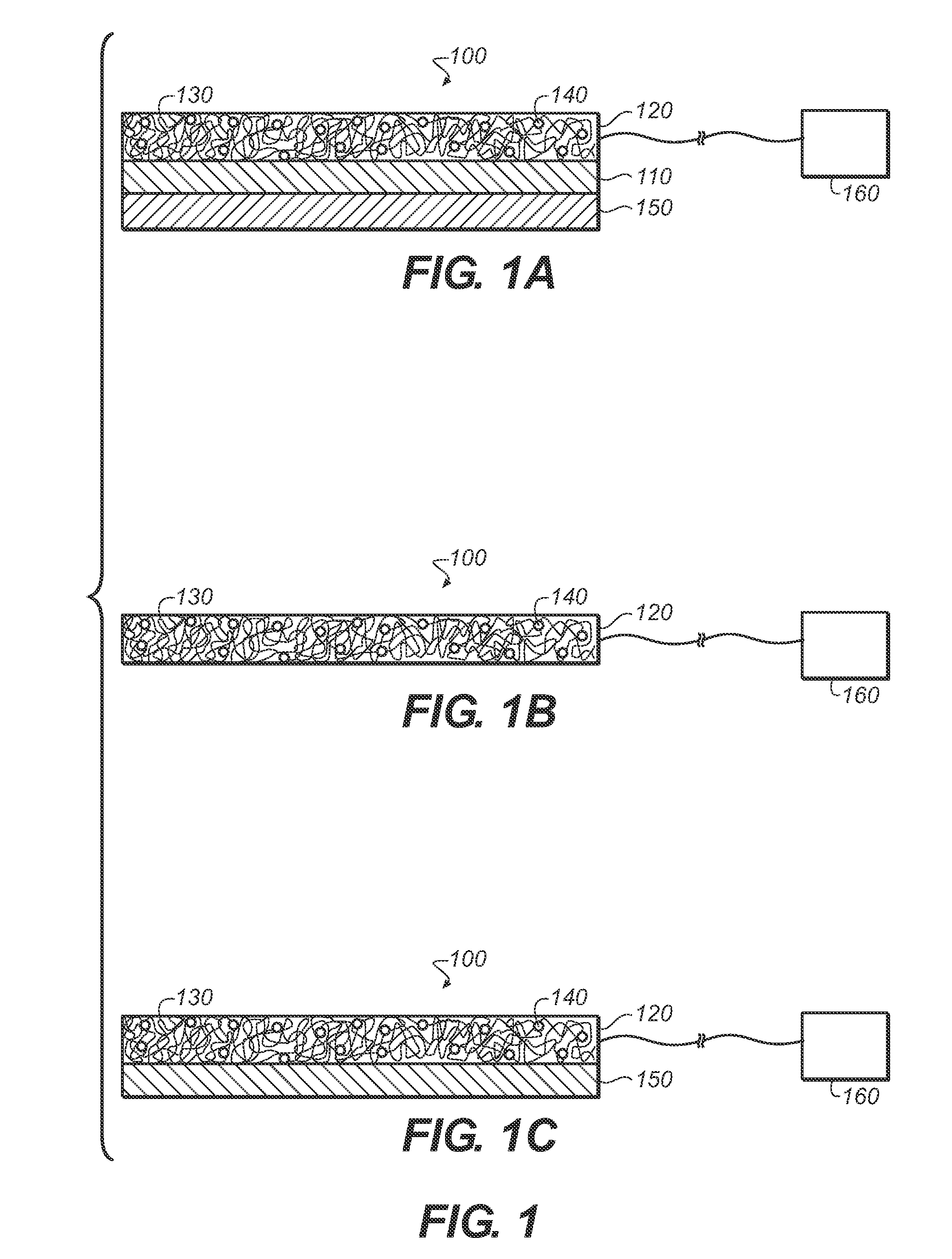
[0035]Composite thermoplastic particles according to the present disclosure were prepared comprising 80 wt. % gadolinium oxysulfide (Gd2O2S) (“GOS”) and 20 wt. % low density polyethylene (LDPE 811A, available from Westlake Chemical Corp. of Houston, Tex.). The GOS powder was loaded into Feeder 2 and the LDPE was loaded into Feeder 4 of a Leistritz twin screw compounder. The die temperature was set to 200° C. and 10 heating zones within the compounder were set to the temperatures shown in Table 1 below:

TABLE 1Zone12345678910Temp (° C.)180190200200190190190190175170

[0036]The screw speed was 300 RPM, and the GOS powder and LDPE were gravity fed into the screw compounder. After exiting the die, the composite thermoplastic particles, comprising LDPE loaded with Gd2O2S, entered a 25° C. water bath to cool and hardened into continuous strands. The strands were then pelletized in a pelletizer and dried at 40° C.

Co-Extrusion of Scintillator Layer an...


PUM

PropertyMeasurementUnit
thicknessaaaaaaaaaa
temperatureaaaaaaaaaa

Abstract

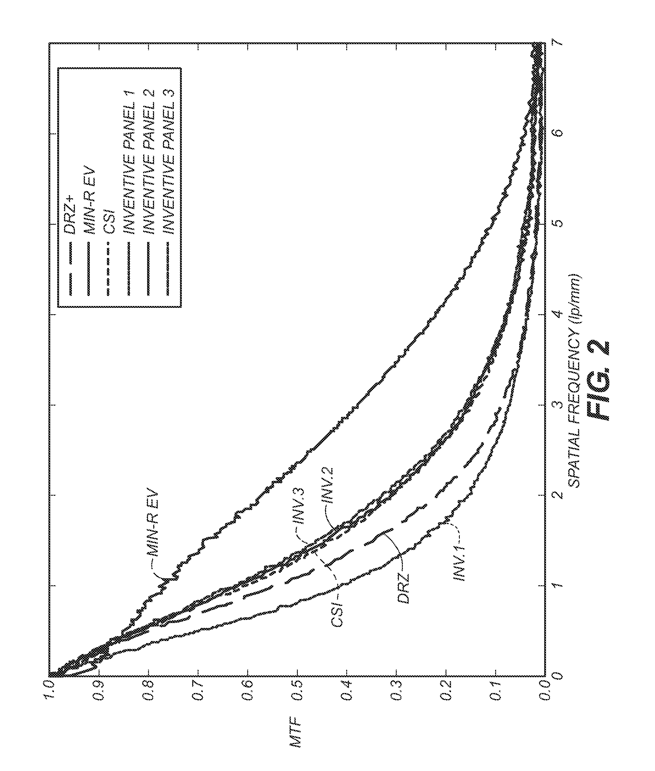
A transparent scintillator panel including an extruded scintillation layer comprising a thermoplastic polyolefin and a scintillator material, wherein the transparent scintillator panel has an intrinsic MTF at least 5% greater than the iH50 of a solvent-coated DRZ+ screen. Also disclosed is a scintillation detection system including a transparent scintillator panel comprising an extruded scintillation layer comprising a thermoplastic olefin and a scintillator material; and at least one photodetector coupled to the transparent scintillator panel, wherein at least one photodetector is configured to detect photons generated from the transparent scintillator panel. Further disclosed is a method of making a transparent scintillator panel including providing thermoplastic particles comprising at least one thermoplastic polyolefin and a scintillator material; and melt extruding the thermoplastic particles to form an extruded scintillation layer.

Description

FIELD OF THE INVENTION[0001]The invention relates generally to the field of scintillation materials, and in particular to extruded scintillation materials including thermoplastic polyolefins and scintillator materials. More specifically, the invention relates to a transparent scintillator panel including an extruded scintillation layer comprising thermoplastic polyolefins and scintillator materials, and method for making the same.BACKGROUND OF THE INVENTION[0002]Scintillators are materials that convert high-energy radiation, such as X-rays and gamma rays, into visible light. Scintillators are widely used in detection and non-invasive imaging technologies, such as imaging systems for medical and screening applications. In such systems, high-energy photons (e.g., X-rays from a radiation source) typically pass through the person or object undergoing imaging and, on the other side of the imaging volume, impact a scintillator associated with a light detection apparatus. The scintillator ...

Claims


Application Information

Patent Timeline
Patent Type & Authority Applications(United States)
IPC IPC(8): G01T1/20B32B5/00C09K11/80B29C47/06C09K11/02C09K11/79B32B27/06B29C47/00
CPCG21K4/00Y10T428/31855
Inventor JAGANNATHAN, SESHADRIYANG, CHANG-YING JOSEPHBISHOP, KEVIN L.PURDUM, MARK S.
Owner CARESTREAM DENTAL TECH TOPCO LTD
Why Eureka
Try Eureka