Fluid-filled vibration-damping device

a technology of vibration damping device and fluid, which is applied in the direction of shock absorbers, machine supports, mechanical equipment, etc., can solve the problems of difficult forming of partition members, high cost, and inability to meet the requirements of fluid structure, so as to achieve the effect of achieve the high-level vibration damping performan

Active Publication Date: 2013-01-03
SUMITOMO RIKO CO LTD
View PDF6 Cites 19 Cited by
  • Summary
  • Abstract
  • Description
  • Claims
  • Application Information

AI Technical Summary

Benefits of technology

[0029]With the seventh mode, for an active type fluid-filled vibration damping device requiring high level vibration damping performance, the manufacture thereof is made easier by the first partition plate and the second partition plate and the movable membrane being combined in advance in air to form the partition member. Also, by preventing air from mixing into the fluid chamber, it is possible to effectively achieve the target high level vibration damping performance.
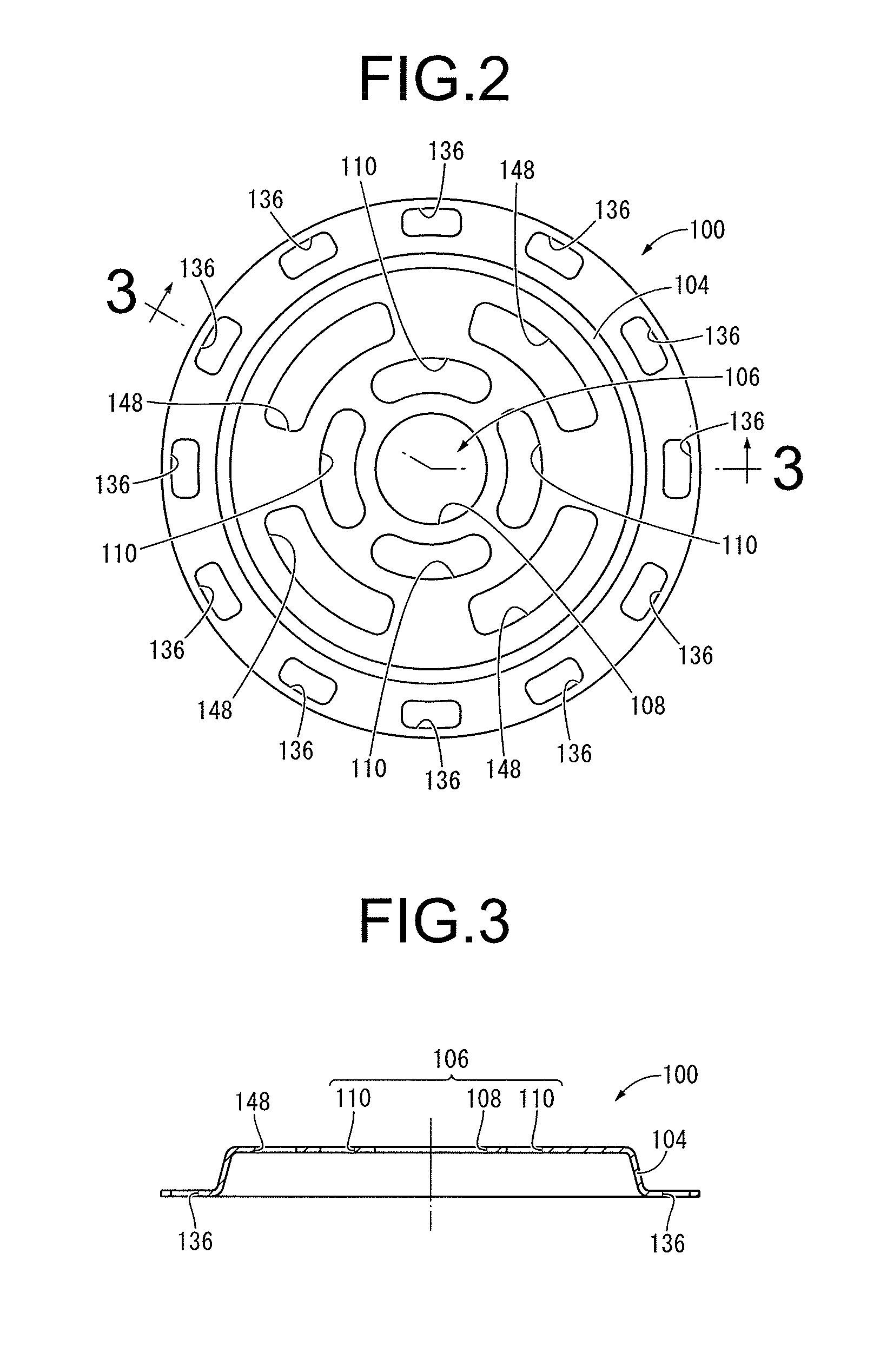
[0030]With the present invention, the partition member is constituted by overlapping the first partition plate and the second partition plate, and the fixing mechanism for fixing the first partition plate and the second partition plate is constituted by latching the claw-shaped part with the circumference edge part of the perforation window. Because of that, by fixing the first partition plate and the second partition plate in air before doing the attachment work of the partition member on the second mounting member which is performed in non-compressible fluid, the work within the non-compressible fluid is simplified, making manufacturing easier. In addition, compared to when doing individual management of the first partition part, the second partition part, and the movable part respectively, parts management and transport is easier. Furthermore, a widening area with the distance between the facing surfaces made partially bigger on the circumference is provided between the outer circumference surface of the movable membrane and the inner circumference surface of the holding area, and also, one of the first partition plate and the second partition plate constituting the partition member has first air vent holes pierced and formed in the part constituting the wall part of the widening area. As a result, when assembling the partition member in air, the air that has entered between the outer circumference surface of the movable membrane and the inner circumference surface of the holding area is easily discharged to the outside through the widening area and the first air vent holes, and air is prevented from remaining in the fluid chamber.

Problems solved by technology

Meanwhile, when the work of combining the first partition plate and the second partition plate (partition forming work) is performed in air, there is the risk that air will remain between the first partition plate and the second partition plate.
Therefore, it is necessary to perform this work inside a water tank filled with the non-compressible fluid, making the partition member forming work difficult.
As a result, complex work is required within fluid.
Therefore, there was the problem that parts management and transport were troublesome.

Method used


Image

  • Fluid-filled vibration-damping device
  • Fluid-filled vibration-damping device
  • Fluid-filled vibration-damping device

Examples


Embodiment Construction

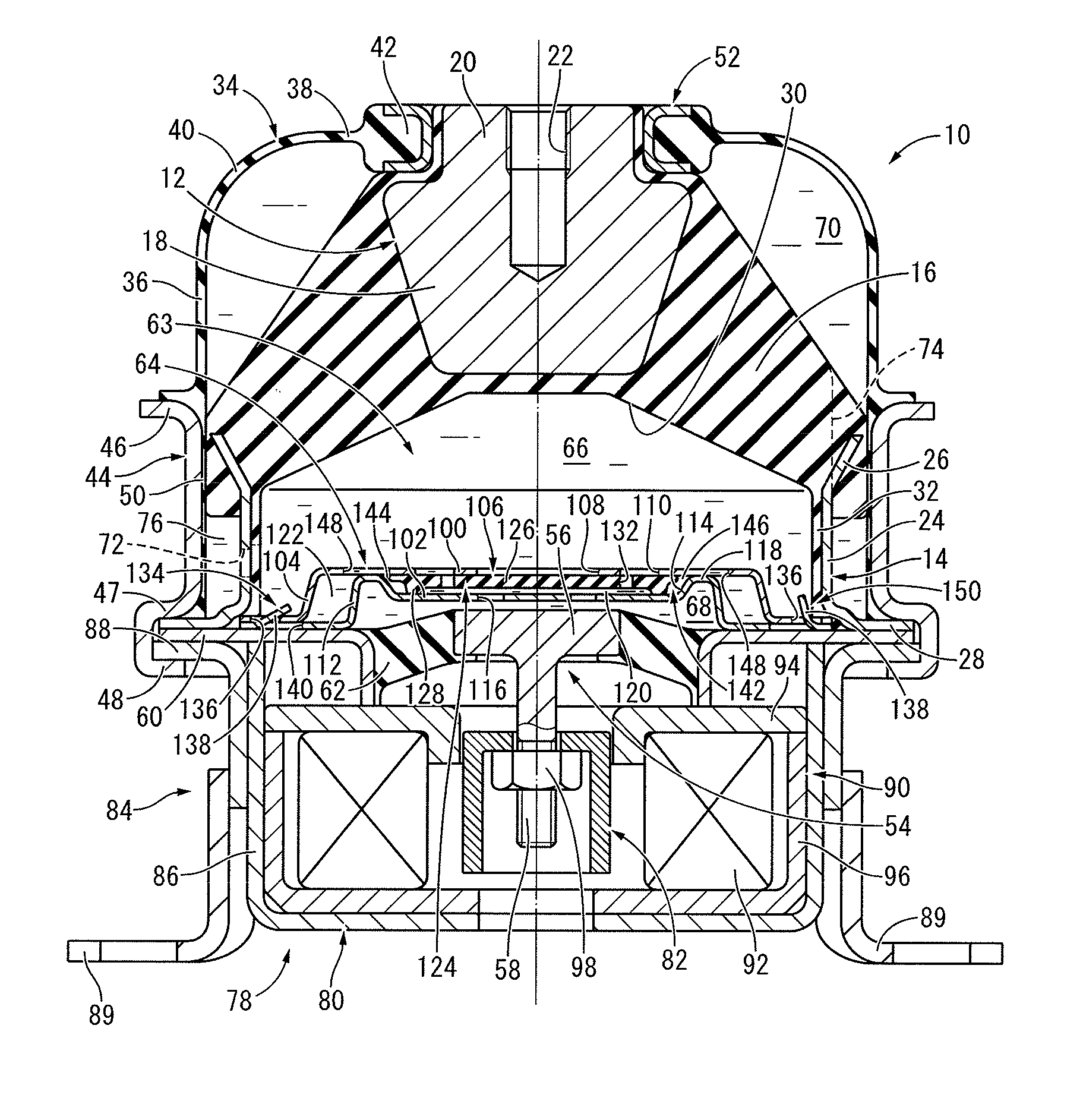
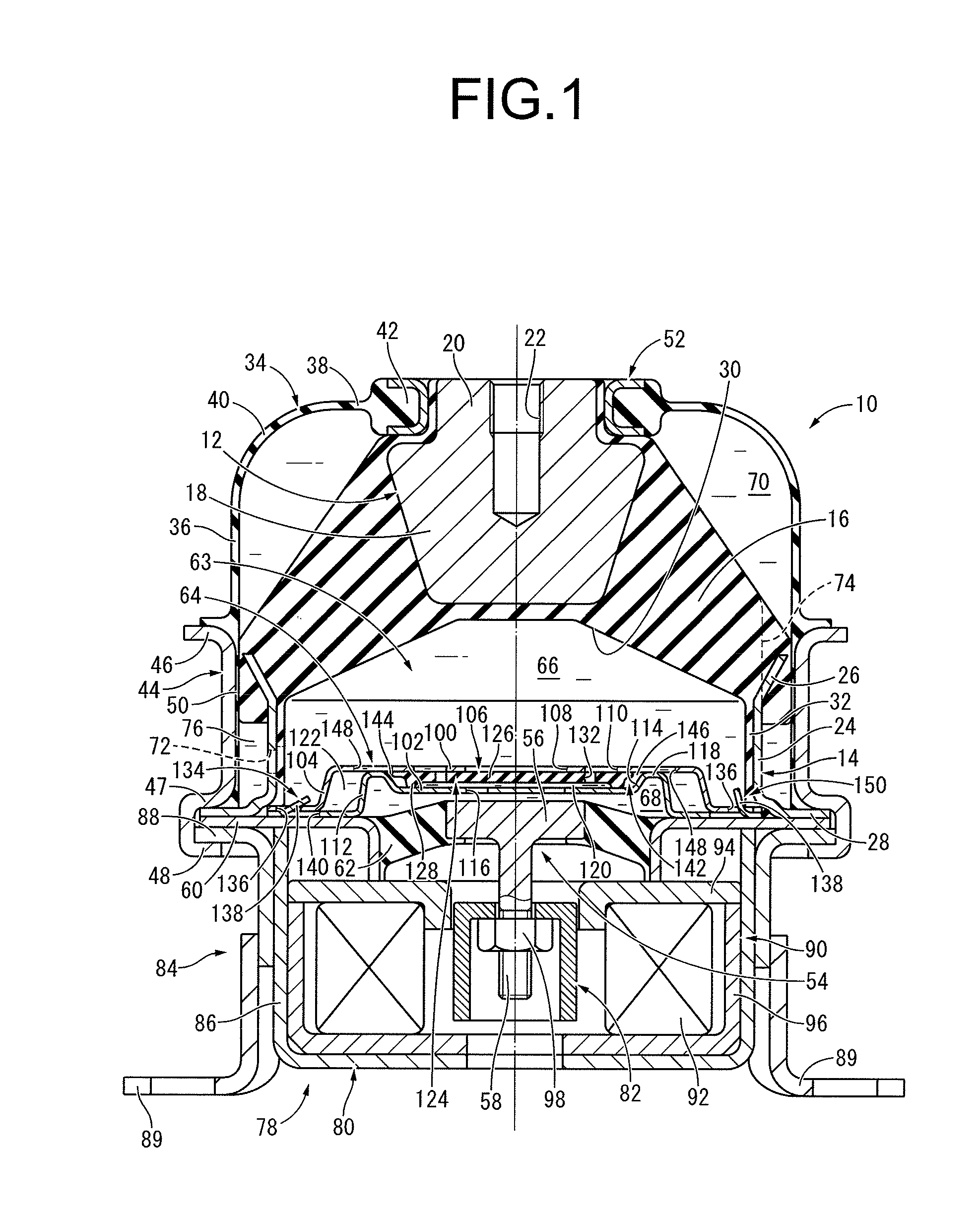
[0045]FIG. 1 shows an automobile engine mount 10 as the first embodiment of the fluid-filled vibration damping device constituted according to the present invention. The engine mount 10 has a constitution for which a first mounting member 12 and a second mounting member 14 are elastically connected by a main rubber elastic body 16, and the first mounting member 12 is attached to a power unit (not shown), and the second mounting member 14 attached to a vehicle body (not shown). With the description below, the up-down direction means the up-down direction in FIG. 1 as a rule.

[0046]More specifically, the first mounting member 12 exhibits overall a small diameter, roughly stepped round column shape, and is equipped with a lower fixing part 18 having a reverse direction, roughly truncated cone shape and a round column shaped upper engaging part 20 projecting facing upward with a smaller diameter than the top end part of the lower fixing part 18 as an integrated unit. Furthermore, a bolt ...


PUM


Abstract

A fluid-filled vibration damping device including: a partition member having first and second partition plates overlapping, and a holding area formed between overlapping surfaces of center parts of the two partition plates; and a movable membrane held and arranged in the holding area. A claw-shaped part and a perforation window are formed at respective corresponding positions of outer circumference parts of the two partition plates, and a fixing mechanism is constituted with the claw-shaped part latched in a circumference edge part of the perforation window. A widening area is provided between an outer circumference surface of the movable membrane and an inner circumference surface of the holding area by partially making a large distance therebetween. At least one of the two partition plates has a first air vent hole piercing a part constituting a wall part of the widening area.

Description

INCORPORATED BY REFERENCE[0001]The disclosure of Japanese Patent Application No. 2011-145053 filed on Jun. 30, 2011 including the specification, drawings and abstract is incorporated herein by reference in its entirety.BACKGROUND OF THE INVENTION[0002]1. Field of the Invention[0003]The present invention relates to a vibration damping device used as an automobile engine mount or the like, for example, and particularly relates to a fluid-filled vibration damping device having a fluid chamber in which non-compressible fluid is enclosed in the interior.[0004]2. Description of the Related Art[0005]Vibration damping devices have been known which are interposed between members constituting a vibration transmission system for connecting these members, or alternatively for supporting one member on the other, in a vibration damping fashion. This vibration damping device includes: a first mounting member attached to one member of the vibration transmission system; a second mounting member atta...

Claims


Application Information

Patent Timeline
Patent Type & Authority Applications(United States)
IPC IPC(8): F16F13/10
CPCF16F13/106
Inventor KANAYA, TOMOHIRO
Owner SUMITOMO RIKO CO LTD
Why Eureka
Try Eureka