Active retrodirective antenna array with a virtual beacon

a virtual beacon and antenna array technology, applied in the direction of antenna details, instruments, antennas, etc., can solve the problems of automatic beam steering in response to an rf signal with a phased array antenna, and achieve the effect of avoiding the rf signal from slipping and slipping

Active Publication Date: 2013-01-03
RAYTHEON CO
View PDF21 Cites 22 Cited by
  • Summary
  • Abstract
  • Description
  • Claims
  • Application Information

AI Technical Summary

Benefits of technology

[0012]In an embodiment, scattering the optical carrier beam off of the target may create multiple virtual beacons at different points on the target. In another embodiment, the optical carrier beam is focused into a spot whose diameter is

Problems solved by technology

Thus, while phased array antennas have been used for some time, automatic beam steering in

Method used


Image

  • Active retrodirective antenna array with a virtual beacon
  • Active retrodirective antenna array with a virtual beacon
  • Active retrodirective antenna array with a virtual beacon

Examples


Embodiment Construction

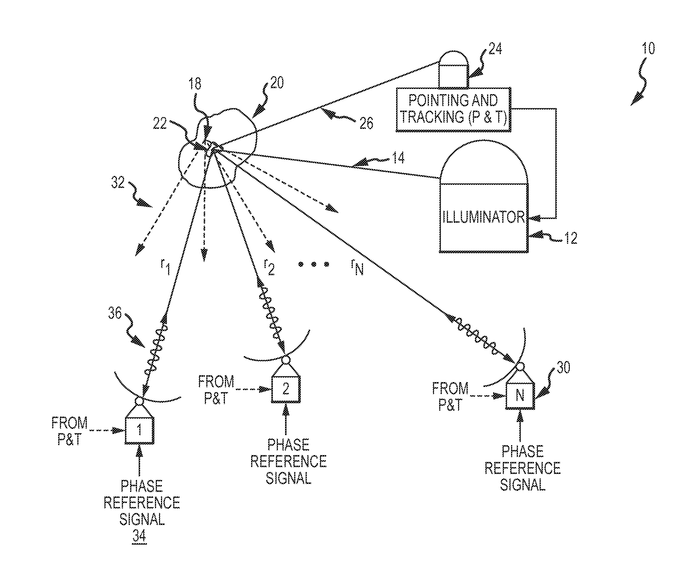
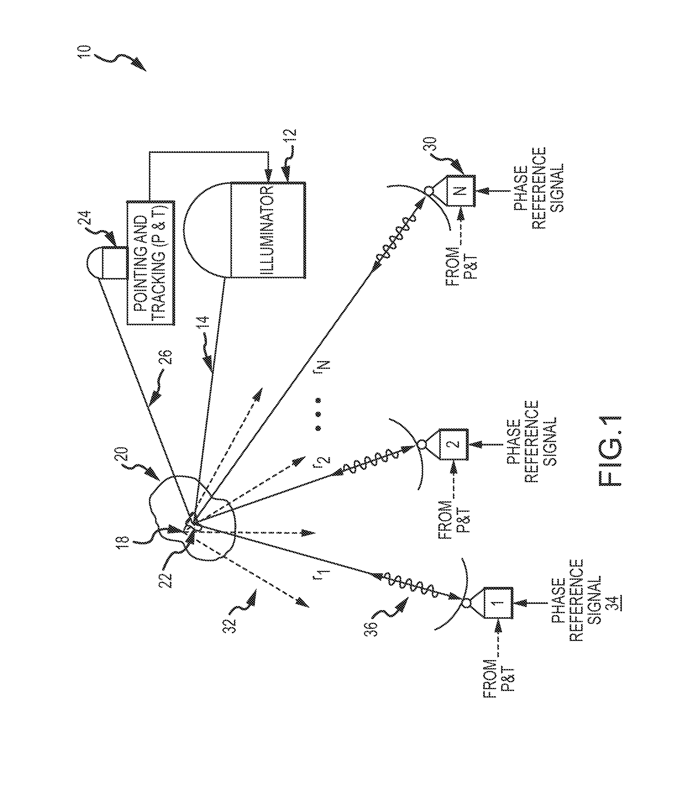
[0030]The present invention provides for an active retrodirective antenna array (ARAA) for use with uncooperative targets. The ARAA automatically tracks the uncooperative target and returns an RF signal to the target. The array may be used to complete an RF communication link, to transfer microwave power from orbiting solar power stations or as a directed energy weapon to prosecute the target.

[0031]An “uncooperative” target is defined as a target that does not itself generate the RF pilot signal through a physical beacon attached to the target. The “uncooperative” target may be friendly such as for power transfer or communications or unfriendly such as for a directed energy weapon. In theory, friendly targets could be fixed with a physical beacon and use conventional ARAA approaches. The “virtual beacon” technique provides flexibility to engage friendly targets without the need for a physical beacon being attached. Unfriendly targets are not going to willingly allow a physical beaco...


PUM


Abstract

An active retrodirective antenna array is provisioned with a virtual beacon for use with uncooperative targets. An RF pilot signal is imposed onto an optical carrier beam and directed at a target. The scattered optical carrier beam is optically detected by a plurality of the retrodirective array nodes to extract the RF pilot signal. Each recovered RF pilot-signal is phase-conjugated with a phase reference signal, amplified and retransmitted towards the target where the RF beams add-in phase at the virtual beacon. The array may be used to complete an RF communication link with the target, to transfer microwave power from orbiting solar power stations to a target or as a directed energy weapon to prosecute the target.

Description

BACKGROUND OF THE INVENTION[0001]1. Field of the Invention[0002]This invention relates to active retrodirective antenna arrays and more particularly to an active retrodirective antenna array (ARAA) that uses an optical carrier beam to reflect an RF pilot signal off a target to create a virtual beacon to individual nodes in the array.[0003]2. Description of the Related Art[0004]For many applications, it is necessary or desirable to be able to automatically track a received signal. In a radar or communication application, for example, it might be useful to be able to track a source of a received signal. A satellite or another RF signal, for example, might be tracked and a return signal automatically transmitted back to the satellite or RF signal source in response thereto. An automatic tracking system might allow for more effective and efficient direction of a return beam to complete an RF signal source or communication link.[0005]Conventionally, beam tracking has involved physically ...

Claims


Application Information

Patent Timeline
IPC IPC(8): G01S13/66G01S13/08H01Q1/00G01S7/4863G01S17/32
CPCG01S17/66G01S17/32G01S7/4863H01Q3/2647
Inventor CROUCH, DAVID D.
Owner RAYTHEON CO
Why Eureka
Try Eureka