Apparatus and method for microwave processing of materials using field-perturbing tool

a technology of material microwave and tool, which is applied in the direction of sustainable building, domestic cooking appliances, electric/magnetic/electromagnetic heating, etc., can solve the problems of insufficient frequency range of fixed-frequency microwave ovens typically found in the home, inability to meet the needs of microwave energy consumption, etc., to achieve the effect of reducing the power density of microwave energy and enhancing efficiency

Inactive Publication Date: 2001-04-24
LOCKHEED MARTIN ENERGY SYST INC
View PDF38 Cites 52 Cited by
  • Summary
  • Abstract
  • Description
  • Claims
  • Application Information

AI Technical Summary

Benefits of technology

A tapered waveguide coupler 68 may be provided to enhance the efficiency with which the broadband microwave energy from the TWT 20 is coupled into the microwave cavity 32. By acting as an impedance transformer between the transmission line from the directional coupler 24 and the microwave cavity 32, this transition increases the percentage power coupled into the microwave cavity 32. In addition, for applications wherein the microwave energy must be coupled into a microwave cavity 32 wherein reactive gases are present, the tapered waveguide 68 provides a means of reducing the power density of the microwave energy at the interface between the microwave input window and reactive gases, thus preventing the formation of plasma discharges at the microwave input window.

Problems solved by technology

However, it is well known that frequencies in this range are not optimal in all situations, such as with heating plasmas, sintering materials such as ceramics, and preparing films such as diamond films.
Further, fixed-frequency microwave ovens typically found in the home are known to have cold spots and hot spots.
With a relatively low frequency microwave introduced into a small cavity, standing waves occur and thus the microwave power does not uniformly fill all of the space within the cavity, and the unaffected regions are not heated.

Method used


Image

  • Apparatus and method for microwave processing of materials using field-perturbing tool
  • Apparatus and method for microwave processing of materials using field-perturbing tool
  • Apparatus and method for microwave processing of materials using field-perturbing tool

Examples


example ii

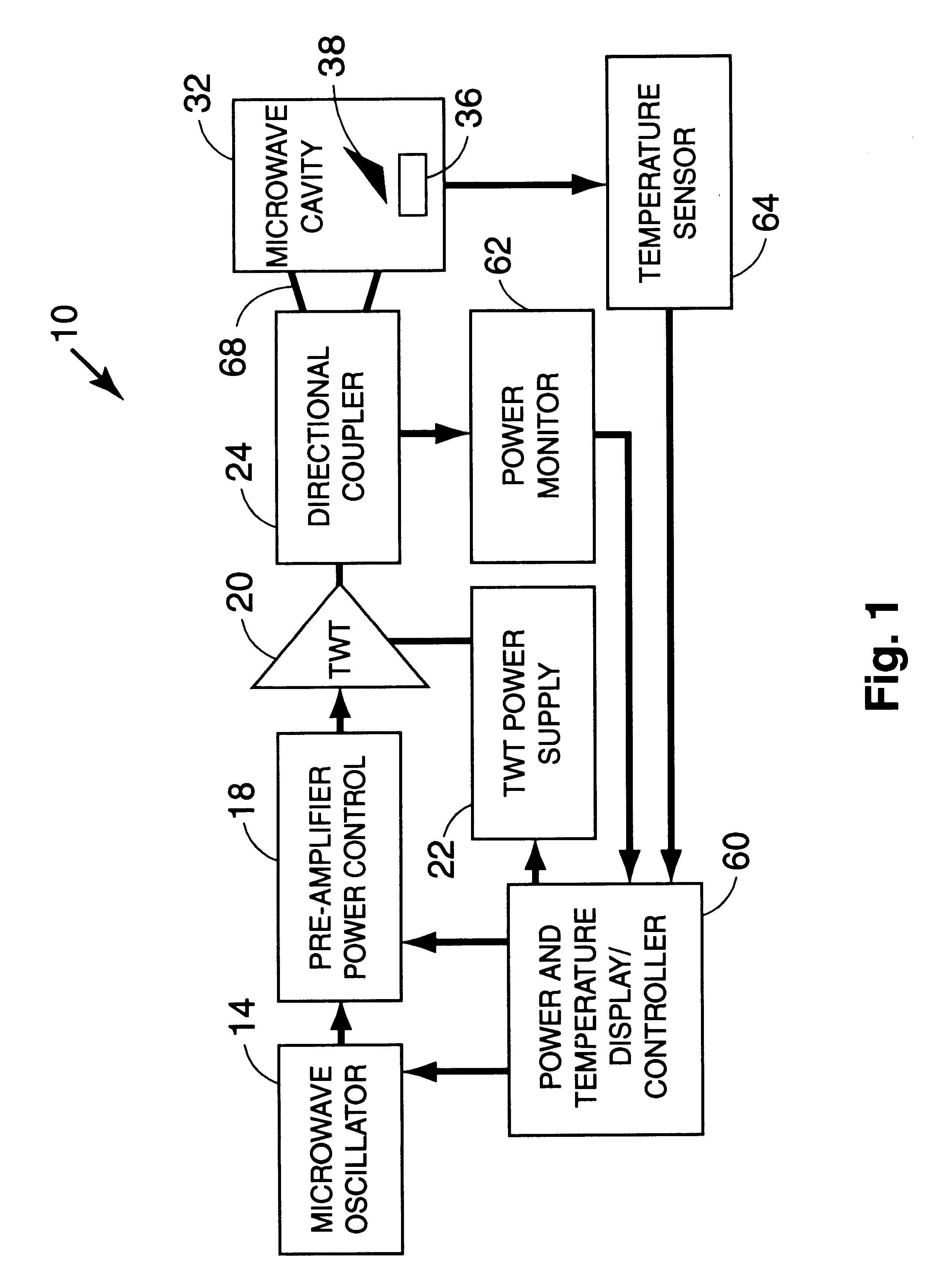
To better determine the limiting factor on required bandwidth, a theoretical model of a 13.times.12.times.10 inch rectangular microwave cavity 32 was constructed and used to determine the number of resonant modes capable of being supported in the cavity over the 4 to 6 GHz frequency range. The results of these calculations clearly demonstrate that, even in a cavity this small, there are an enormous number (over 600) of possible, closely-spaced modes (often 3 to 4 at a single frequency) over even the 4 to 6 GHz frequency range. These results have been graphically illustrated in FIG. 3 as mode density versus frequency. From these results, it is clear that a bandwidth of as little as 5% of the center frequency could, in some cases, provide sufficient mode plurality to provide relatively uniform baseline energy distribution in the microwave cavity.

Using this theoretical model, power density was calculated as a function of location at various points along a horizontal midplane of the (em...

example iii

A plasma chamber was constructed including a glass bell jar for observing the excitation of plasmas in mixtures of hydrogen and methane. The microwave source was a Microwave Laboratories, Inc. 4-8 GHz, T-1096 traveling wave tube, launching from the side into a multimode cavity. The atmosphere was about 0.9% CH.sub.4 in H.sub.2 at a pressure of about 28 torr. Steel drill bits 50 were placed in the bell jar with their tips upward and the TWT was operated at 1200 W forward power, sweeping the frequency from 4.1 to 6.7 GHz approximately 10 times per second. Surprisingly, plasmas 51 ignited stably at the tip of each drill bit as shown schematically in FIG. 5. This phenomenon occurred even with more than eight drill bits of differing sizes present in the chamber. This example illustrates how selected perturbations can be introduced into the uniform power environment of the variable frequency microwave system with predictable, controllable, and stable results. Diamond 52 can be selectively...

example iv

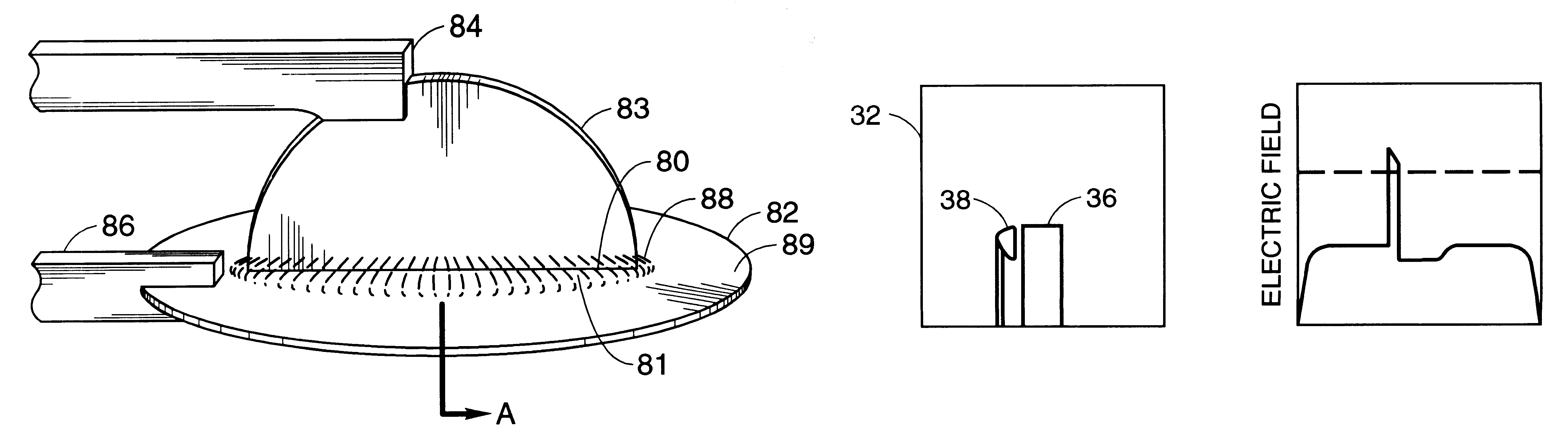
In a system similar to that in the preceding example, a silicon wafer 70 was placed horizontally on a pedestal as shown in cross section in FIG. 6a. Plasma 71 ignited uniformly around the periphery of the wafer, selectively depositing diamond 72 as shown. An improved setup, shown in FIG. 6b, used a field-perturbing tool 73 with a graded impedance to reduce the tendency for selective plasma discharge by equalizing the electric field in the vicinity of the wafer 70.

The field-perturbing tool 73 comprises an alumina base layer 74, an alumina-silicon carbide intermediate layer 75, and a silicon carbide top layer 76.

The field-perturbing 73 tool illustrated in FIG. 6b was constructed as a demonstration of the potential of the field-perturbing tool and associated method to equalize the power distribution around a workpiece containing a physical discontinuity as illustrated theoretically in FIG. 14. Skilled artisans will appreciate that the technique could be used to create even more optimal...


PUM

PropertyMeasurementUnit
frequencyaaaaaaaaaa
frequenciesaaaaaaaaaa
frequencyaaaaaaaaaa

Abstract

A variable frequency microwave heating apparatus designed to allow modulation of the frequency of the microwaves introduced into a multi-mode microwave cavity for heating or other selected applications. A field-perturbing tool is disposed within the cavity to perturb the microwave power distribution in order to apply a desired level of microwave power to the workpiece.

Description

The present invention relates to applications of microwave energy for processing materials, and more particularly to the use of tooling within the microwave cavity of a variable-frequency microwave furnace in order to selectively vary the microwave power applied to the workpiece.In the field of microwave energy, it is well known that microwave ovens, furnaces, and the like are typically constructed with a fixed operating frequency. It has long been known that the interactions of various materials with microwaves are frequency dependent. These interactions may include curing rubber and sintering ceramics. It is therefore desirable to have a microwave furnace that can be operated over a broad frequency range.Typical microwave energy sources have a very narrow bandwidth because they employ a resonant cavity. For example, microwave ovens constructed for home use are provided with a magnetron which operates at 2.45 GHz, which is a frequency that has been allocated by the FCC for domestic...

Claims


Application Information

Patent Timeline
Patent Type & Authority Patents(United States)
IPC IPC(8): H05B6/74
CPCH05B6/686H05B6/705H05B6/806Y02B40/143Y02B40/00
Inventor TUCKER, DENISE A.FATHI, ZAKARYAELAUF, ROBERT J.
Owner LOCKHEED MARTIN ENERGY SYST INC
Why Eureka
Try Eureka