Ink jet recording apparatus and recorded article
- Summary
- Abstract
- Description
- Claims
- Application Information
AI Technical Summary
Benefits of technology
Problems solved by technology
Method used
Image
Examples
first embodiment
5.2.1. First Embodiment
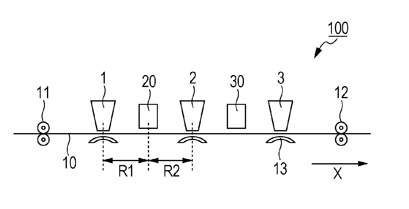
[0122]FIG. 1 is a schematic view of an ink jet recording apparatus 100 according to a first embodiment. The ink jet recording apparatus 100 records an image on a recording medium 10 by an ink jet recording method. The ink jet recording apparatus 100 includes a first, a second and a third line head 1 to 3, transport mechanisms 11 and 12, guides 13, an irradiation portion 20, and a heating portion 30. Also, the ink jet recording apparatus 100 further includes a control board and an ink container (each not shown) in an apparatus body.
[0123]The recording medium 10, supported on the guides 13, is moved within the apparatus body by the transport mechanisms 11 and 12. One transport mechanism 11 is disposed upstream in the direction in which the recording medium 10 is moved (X direction in FIG. 1, hereinafter referred to as the moving direction of the recording medium), and the other transport mechanism 12 is disposed downstream of the apparatus. However, the position...
second embodiment
5.2.2. Second Embodiment
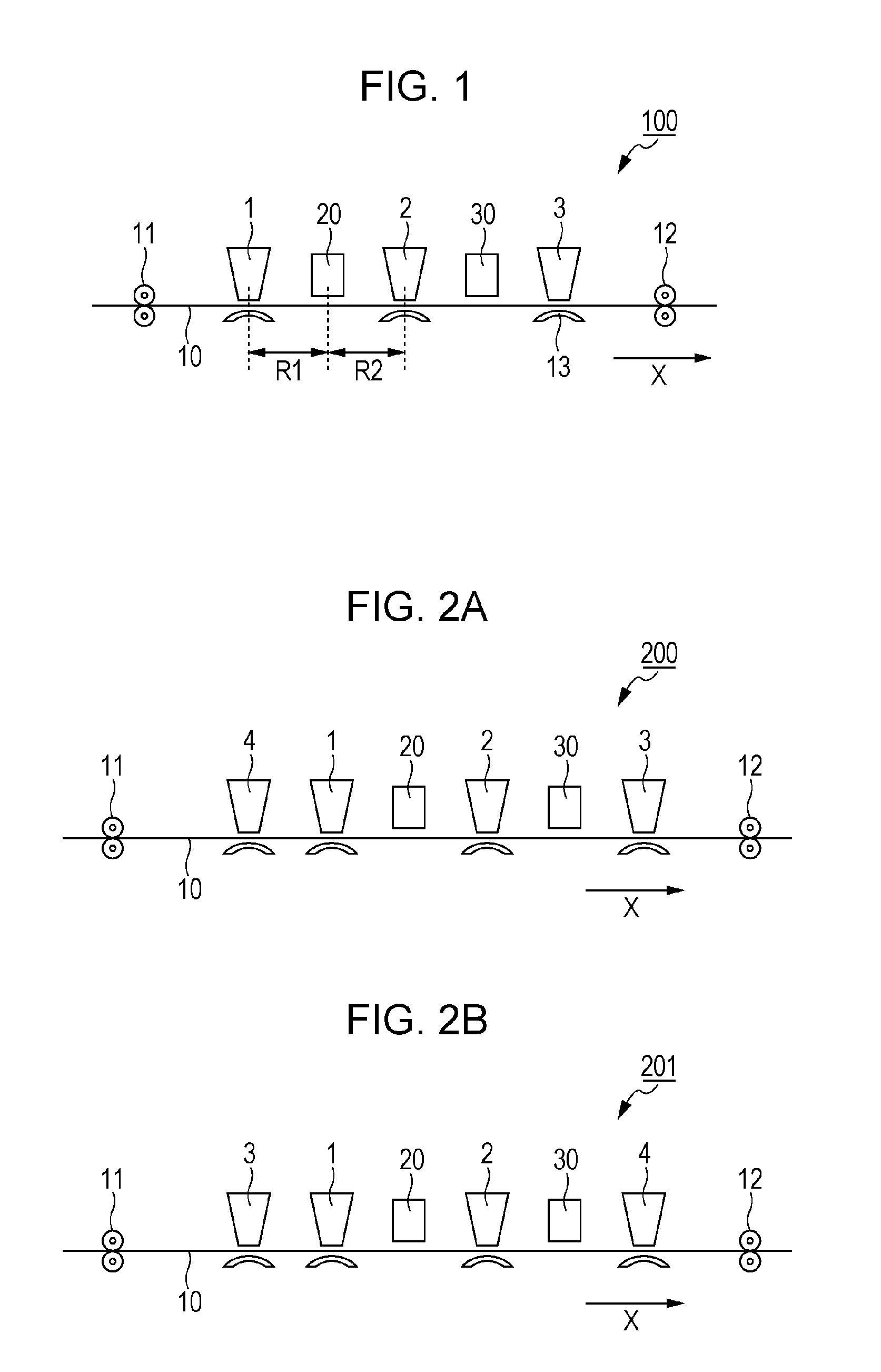
[0136]FIGS. 2A and 2B are schematic views of ink jet recording apparatuses 200 and 201 according to a second embodiment. The ink jet recording apparatus 200 includes the structure of the first embodiment, and this structure is further provided with a fourth line head 4, as shown in FIG. 2A. The ink jet recording apparatus 200 has the same structure as in the first embodiment except that the fourth line head 4 is disposed upstream from the first line head 1 in the moving direction of the recording medium 10. The fourth line head 4 has many ejection nozzles aligned in a line in a direction intersecting the X direction. The fourth line head 4 ejects a white-type ink delivered from the ink container.
[0137]In this structure, since the fourth line head 4 is disposed upstream from the first line head 1 in the moving direction of the recording medium 10, the layer of the polymerizable ink is formed on the white-type ink ejected from the fourth line head 4.
[0138]Glitt...
third embodiment
5.2.3. Third Embodiment
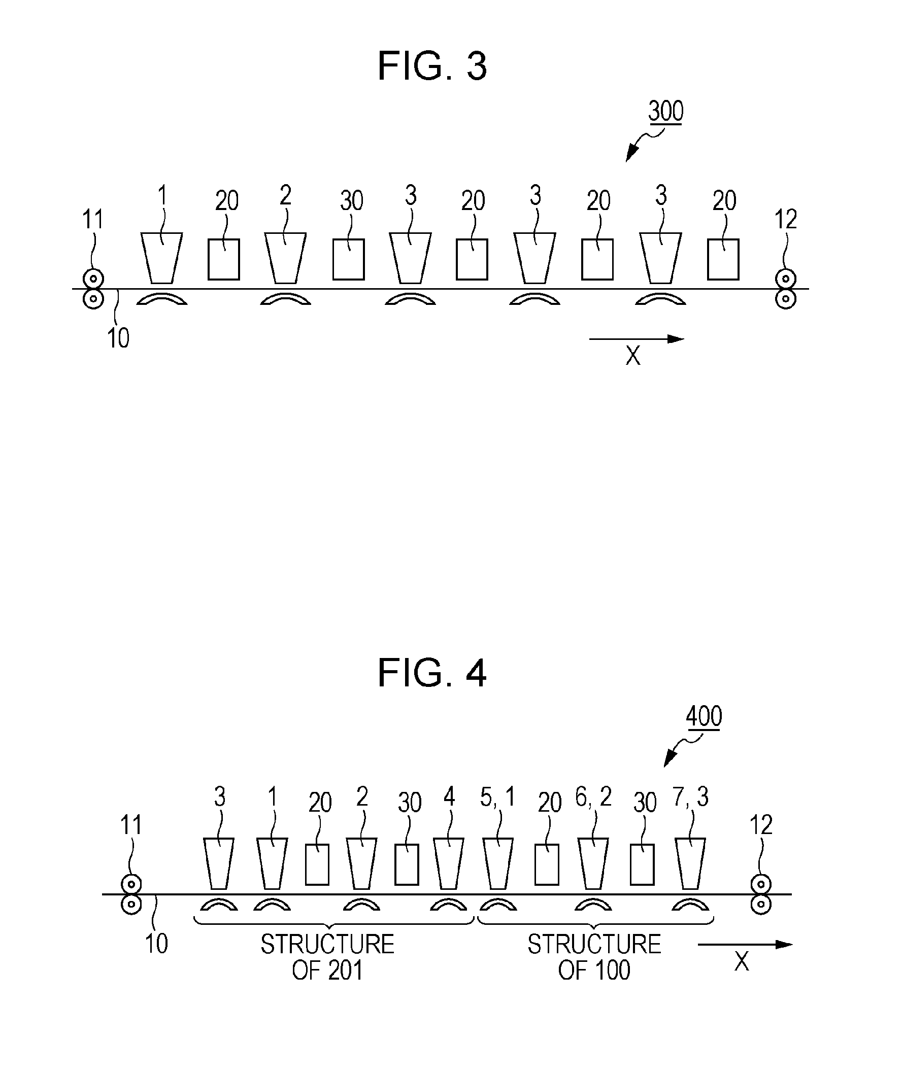
[0143]FIG. 3 is a schematic view of an ink jet recording apparatus 300 according to a third embodiment. The structure of the present embodiment is suitable for forming an image with a coloring ink containing an active energy radiation-polymerizable compound. In the ink jet recording apparatus 300, as shown in FIG. 3, two additional third line heads 3 are disposed downstream from the structure of the first embodiment in the moving direction of the recording medium 10. Each of the third line heads 3, including the line head 3 originally disposed in the structure of the first embodiment, is provided with an irradiation portion 20 downstream therefrom. The number of sets of the third line head 3 and the corresponding irradiation portion 20 disposed downstream of the third line head 3 is not limited to three as above, and may be increased according to the type of the coloring ink used. When the glittering ink substantially does not contain a polymerizable ink, the ...
PUM
 Abstract
Description
Claims
Application Information
 - R&D
- Intellectual Property
- Life Sciences
- Materials
- Tech Scout
- Unparalleled Data Quality
- Higher Quality Content
- 60% Fewer Hallucinations
Browse by: Latest US Patents, China's latest patents, Technical Efficacy Thesaurus, Application Domain, Technology Topic, Popular Technical Reports.
© 2025 PatSnap. All rights reserved.Legal|Privacy policy|Modern Slavery Act Transparency Statement|Sitemap|About US| Contact US: help@patsnap.com


