Method and system for scatter correction in x-ray imaging

a scatter correction and x-ray imaging technology, applied in the field of scatter correction in x-ray imaging, can solve the problems of -dimensional (2d) grids, scatter may manifest as noise or artifacts, and artifacts or other imperfections in the reconstructed image, and achieve the effect of reducing complexity and cos

Active Publication Date: 2013-01-03
GENERAL ELECTRIC CO
View PDF3 Cites 15 Cited by
  • Summary
  • Abstract
  • Description
  • Claims
  • Application Information

AI Technical Summary

Benefits of technology

[0003]In one embodiment, a method for estimating scatter is provided. In accordance with this method, an initial volume is generated based on X-ray transmission from a source to a detector. A plurality of voxels is characterized within the initial volume based on material type. A density integrated volume is generated based on the plurality of voxels characterized based on material type. One or more scattered X-rays are tracked beginning at the detector and proceeding toward the source to generate a scatter profile for a plurality of discrete locations on the detector.
[0004]In a further embodiment, an image processing system is provided. The image processing system includes a memory storing one or more routi

Problems solved by technology

However, various physical limitations or constraints on acquisition may result in artifacts or other imperfections in the reconstructed image.
Such scatter may manifest as either noise or artifacts in the reconstructed images

Method used


Image

  • Method and system for scatter correction in x-ray imaging
  • Method and system for scatter correction in x-ray imaging
  • Method and system for scatter correction in x-ray imaging

Examples


Embodiment Construction

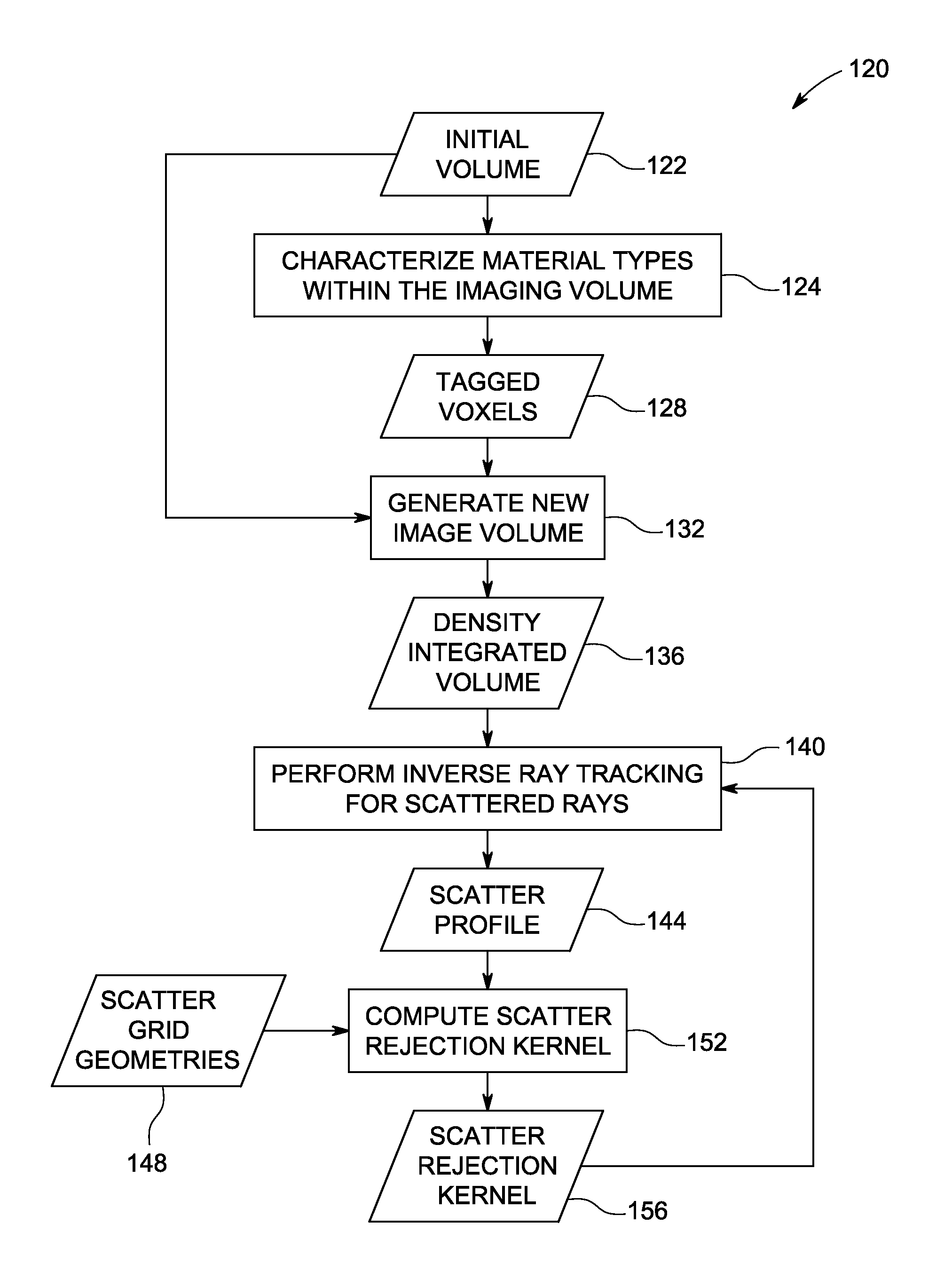
[0015]In instances where one-dimensional or two-dimensional anti-scatter grids are employed, computational scatter correction based on image processing may still be utilized to further suppress image artifacts due to scatter and to achieve good image quality. Without an accurate scatter correction algorithm, the resulting image artifacts attributable to scatter effects can be detrimental. In the present disclosure, a physics model based correction algorithm and its use for scatter artifact suppression is described.

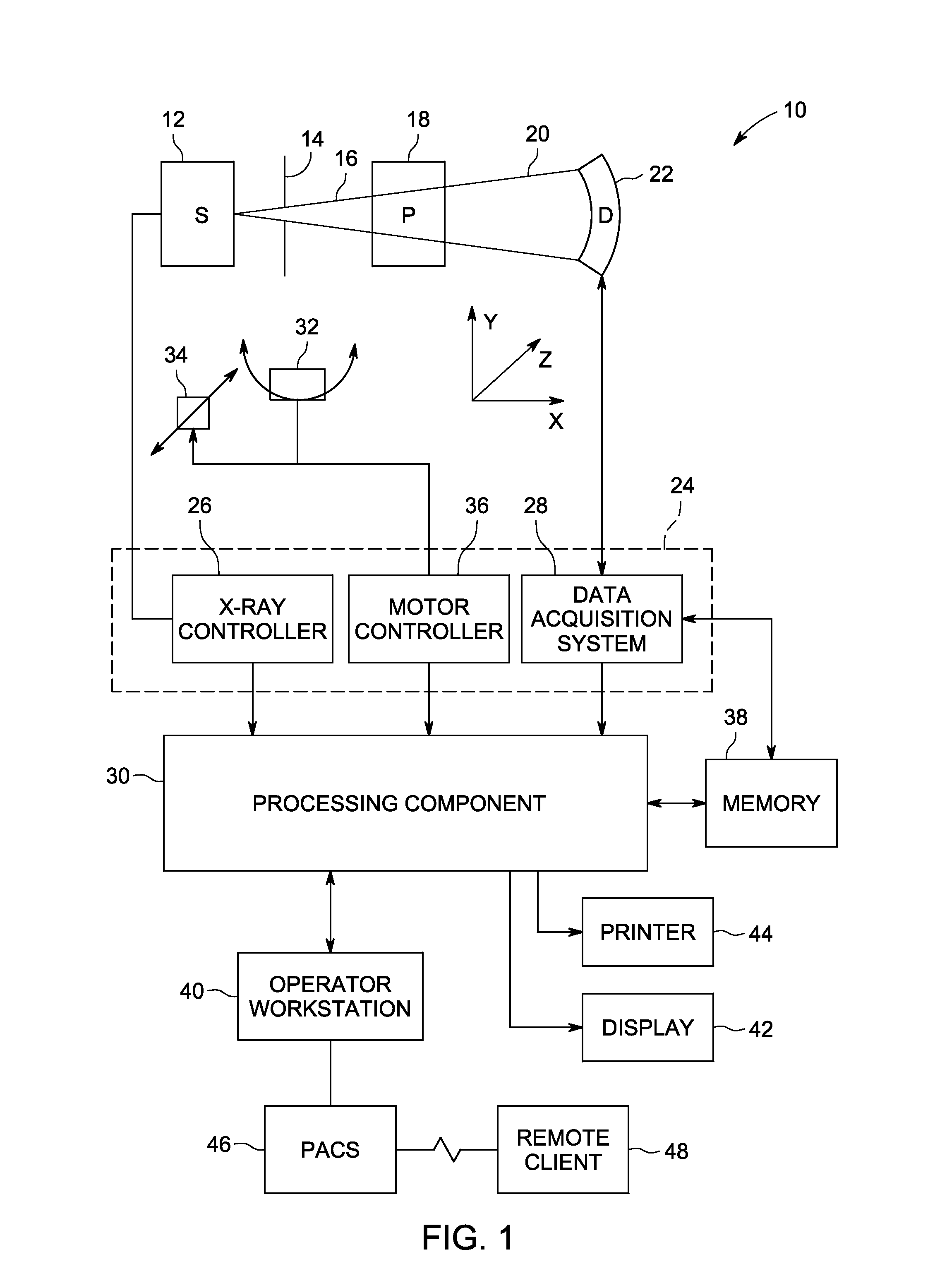
[0016]With this in mind, an example of a computed tomography (CT) imaging system 10 designed to acquire X-ray attenuation data at a variety of views around a patient and suitable for tomographic reconstruction is provided in FIG. 1. In the embodiment illustrated in FIG. 1, imaging system 10 includes a source of X-ray radiation 12 positioned adjacent to a collimator 14. The X-ray source 12 may be an X-ray tube, a distributed X-ray source (such as a solid-state or thermionic...


PUM


Abstract

Approaches for deriving scatter information using inverse tracking of scattered X-rays is disclosed. In certain embodiments scattered rays are tracked from respective locations on a detector to a source of the X-ray radiation, as opposed to tracking schemes that proceed from the source to the detector. In one such approach, the inverse tracking is implemented using a density integrated volume that reduces the integration steps performed.

Description

BACKGROUND[0001]Non-invasive imaging technologies allow images of the internal structures of a patient or object to be obtained without performing an invasive procedure on the patient or object. In particular, technologies such as computed tomography (CT) use various physical principles, such as the differential transmission of X-rays through the target volume, to acquire image data and to construct tomographic images (e.g., three-dimensional representations of the interior of the human body or of other imaged structures). However, various physical limitations or constraints on acquisition may result in artifacts or other imperfections in the reconstructed image.[0002]For example, in a wide-cone X-ray CT system, the ratio of the signal attributable to scatter relative to the primary signal may be high. Such scatter may manifest as either noise or artifacts in the reconstructed images. Proper scatter mitigation may include both scatter rejection and the use of anti-scatter grids. One...

Claims


Application Information

Patent Timeline
IPC IPC(8): G06K9/00
CPCA61B6/032A61B6/06A61B6/4085A61B6/5282A61B6/483A61B6/5205A61B6/4291
Inventor WU, XIAOYEHSIEH, JIANGSAINATH, PAAVANALIU, XIN
Owner GENERAL ELECTRIC CO
Why Eureka
Try Eureka