Charging member, process cartridge and electrophotographic apparatus

a technology of electrophotographic apparatus and charging member, which is applied in the direction of electrographic process apparatus, instruments, corona discharge, etc., can solve the problems of oxidation of the surface of the charging member, the inability to charge the electrophotographic photosensitive member stably and surely, and the inability to easily change the charging performance with time, so as to achieve stable formation of high-grade electrophotographic images, the effect of superior charging performan

Inactive Publication Date: 2013-01-03
CANON KK
View PDF5 Cites 33 Cited by
  • Summary
  • Abstract
  • Description
  • Claims
  • Application Information

AI Technical Summary

Benefits of technology

[0016]According to the present invention, a charging member can also be obtained which has a superior charging performance for the electrophotographic photosensitive member and also can not easily change with time in charging performance.
[0017]According to the present invention, an electrophotographic apparatus and a process cartridge can also be obtained which enable stable formation of high-grade electrophotographic images.
[0018]Further features of the present invention will become apparent from the following description of exemplary embodiments with reference to the attached drawings.

Problems solved by technology

Now, as electrophotographic image formation processes have become higher in speed and apparatus therefor have become longer in lifetime in recent years, the time for contact between the electrophotographic photosensitive member and the charging member has become relatively short, and this trends disadvantageously for charging the electrophotographic photosensitive member stably and surely.
Hence, where the charging member is continued being used over a long period of time, the surface of the charging member may be oxidized to come to deteriorate gradually and change with time in charging performance.

Method used

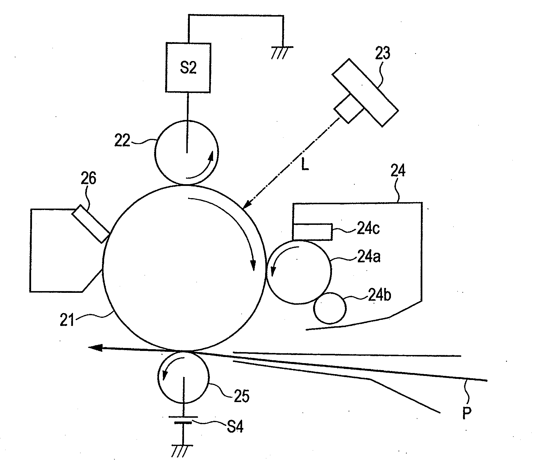
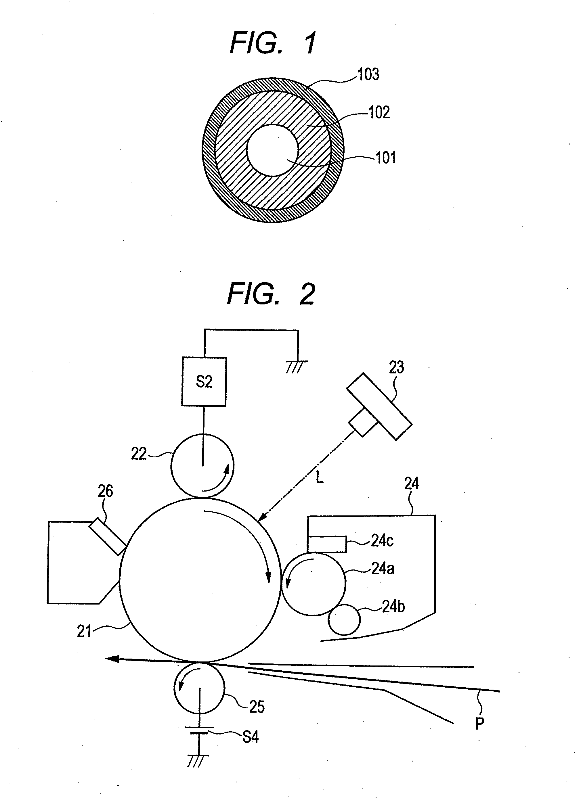

Image

  • Charging member, process cartridge and electrophotographic apparatus
  • Charging member, process cartridge and electrophotographic apparatus
  • Charging member, process cartridge and electrophotographic apparatus

Examples


example 1

(1) Formation & Evaluation of Conductive Elastic Layer

[0182]

TABLE 1Amount[part(s)Raw materialsby mass]Medium / high-nitrile NBR (trade name: NIPOL100DN219; available from Nippon Zeon Co., Ltd.)Bound acrylonitrile content center value:33.5%; Mooney viscosity center value: 27Carbon black for color (filler) (trade name:48#7360SB; available from Tokai Carbon Co.,Ltd.)Particle diameter: 28 nm; nitrogenadsorption specific surface area: 77 m2 / g;DBP oil absorption: 87 cm3 / 100 gCalcium carbonate (filler) (trade name:20NANOX #30; available from Maruo Calcium Co.,Ltd.)Zinc oxide5Stearic acid1

[0183]Materials shown in Table 1 were mixed by means of a 6-liter volume pressure kneader (trade name: TD6-15MDX; manufactured by Toshin Co., Ltd.) for 24 minutes in a packing of 70 vol. % and at a number of blade revolutions of rpm to obtain an unvulcanized rubber composition. To 174 parts by mass of this unvulcanized rubber composition, 4.5 parts of tetrabenzylthiuram disulfide (trade name: SANCELER TBzTD;...

examples 2 to 23

(1) Preparation & Evaluation of Condensates Nos. 2 to 23

[0227]Condensate intermediates 2 to 7 were prepared in the same way as the condensate intermediate 1 in Example 1 except that they were composed as shown in Table 9 below. Next, condensates 2 to 23 were prepared in the same way as the condensate 1 in Example 1 except that they were composed as shown in Table 10 below. Evaluation was made in the same way as the method described in Evaluation (1) in Example 1 except that the respective condensates obtained were used. Results obtained are shown in Table 12.

TABLE 9Synthesis 1CondensateComponent (A)Component (B)intermediateEP-1EP-2EP-3EP-4HePhNo.(g)(g)(g)(g)(g)(g)111.56———62.11—238.35———33.53—361.70———8.78—412.22———15.2756.925—9.84——64.95—6——14.98—59.63—7———11.9361.40—

[0228]Here, abbreviation symbols EP-1 to EP-5, He and Ph in the columns of the components (A) and (B) in Table 9 and also an abbreviation symbol Ti-1 to Ti-3 in the column of the component (C) in Table 10 represent the...


PUM


Abstract

A charging member for electrophotographic apparatus is provided which has a superior charging performance for the electrophotographic photosensitive member and also can not easily change with time in charging performance. The charging member has a substrate, an elastic layer and a surface layer, which surface layer contains a high-molecular compound having an Si—O—Ti linkage in the molecular structure and a cyclic polysilane represented by the general formula (7) defined in the specification, and the high-molecular compound has a constituent unit represented by the general formula (1) and a constituent unit represented by the following formula (2) which are defined in the specification.

Description

CROSS-REFERENCE TO RELATED APPLICATIONS[0001]This application is a continuation of International Application No. PCT / JP2012 / 002686, filed Apr. 18, 2012, which claims the benefit of Japanese Patent Application No. 2011-097477, filed Apr. 25, 2011.BACKGROUND OF THE INVENTION[0002]1. Field of the Invention[0003]This invention relates to a charging member used in contact charging of electrophotographic apparatus, and to a process cartridge and an electrophotographic apparatus.[0004]2. Related Background Art[0005]A charging member provided in contact with an electrophotographic photosensitive member to charge the electrophotographic photosensitive member electrostatically is commonly so constituted as to have an elastic layer containing a rubber, in order to sufficiently and uniformly secure a contact nip between the electrophotographic photosensitive member and the charging member. In such an elastic layer, a low-molecular weight component is inevitably contained, and hence the low-mole...

Claims


Application Information

Patent Timeline
Patent Type & Authority Applications(United States)
IPC IPC(8): G03G15/02
CPCG03G15/0233G03G15/02
Inventor KURODA, NORIAKIKODAMA, MASATAKASUZUMURA, NORIKOTOMOMIZU, YUYAMASU, HIROKI
Owner CANON KK
Why Eureka
Try Eureka