Well Pump with Seal Section Having a Labyrinth Flow Path in a Metal Bellows

a technology of labyrinth flow path and well pump, which is applied in the direction of piston pump, positive displacement liquid engine, borehole/well accessories, etc., can solve the problems of encroaching well fluid particularly, affecting the flow path of encroaching well fluid into the motor,

Inactive Publication Date: 2013-01-03
BAKER HUGHES INC
View PDF5 Cites 31 Cited by
  • Summary
  • Abstract
  • Description
  • Claims
  • Application Information

AI Technical Summary

Benefits of technology

[0008]Preferably, the lower lubricant communication passage is sealed from an inner annular space between the guide tube and the shaft. Also, the upper portion of the guide tube passage is sealed from the inner annular space between the shaft and the guide tube. The guide tube passage may be a cylindrical bore extending parallel with an axis of the guide tube and having a diameter less than a radial thickness of the guide tube from the interior to the exterior of the guide tube.
[0009]The flexible member may be a bellows with a larger diameter portion and a smaller diameter portion, the smaller diameter portion extending into the larger diameter portion and having an inner side in substantial contact with the exterior of the guide tube. In the embodiment shown, the smaller diameter portion defines an upper end of the bellows.
[0010]An upper seal is mounted between the upper adapter and the shaft. A top cap may be secured to a lower side of the upper adapter below the seal. An upper end of the guide tube is secured sealingly to the top cap, isolating the exterior of the guide tube from an inner annular space between the guide tube and the shaft.
[0011]...

Problems solved by technology

Typically, some well fluid will leak past these seals and eventually enter the lubricant chamber of the flexible member.
Encroaching well fluid may particularly be a problem in wells that are inclined.
The lubricant is normally lighter than the well...

Method used


Image

  • Well Pump with Seal Section Having a Labyrinth Flow Path in a Metal Bellows
  • Well Pump with Seal Section Having a Labyrinth Flow Path in a Metal Bellows
  • Well Pump with Seal Section Having a Labyrinth Flow Path in a Metal Bellows

Examples


Embodiment Construction

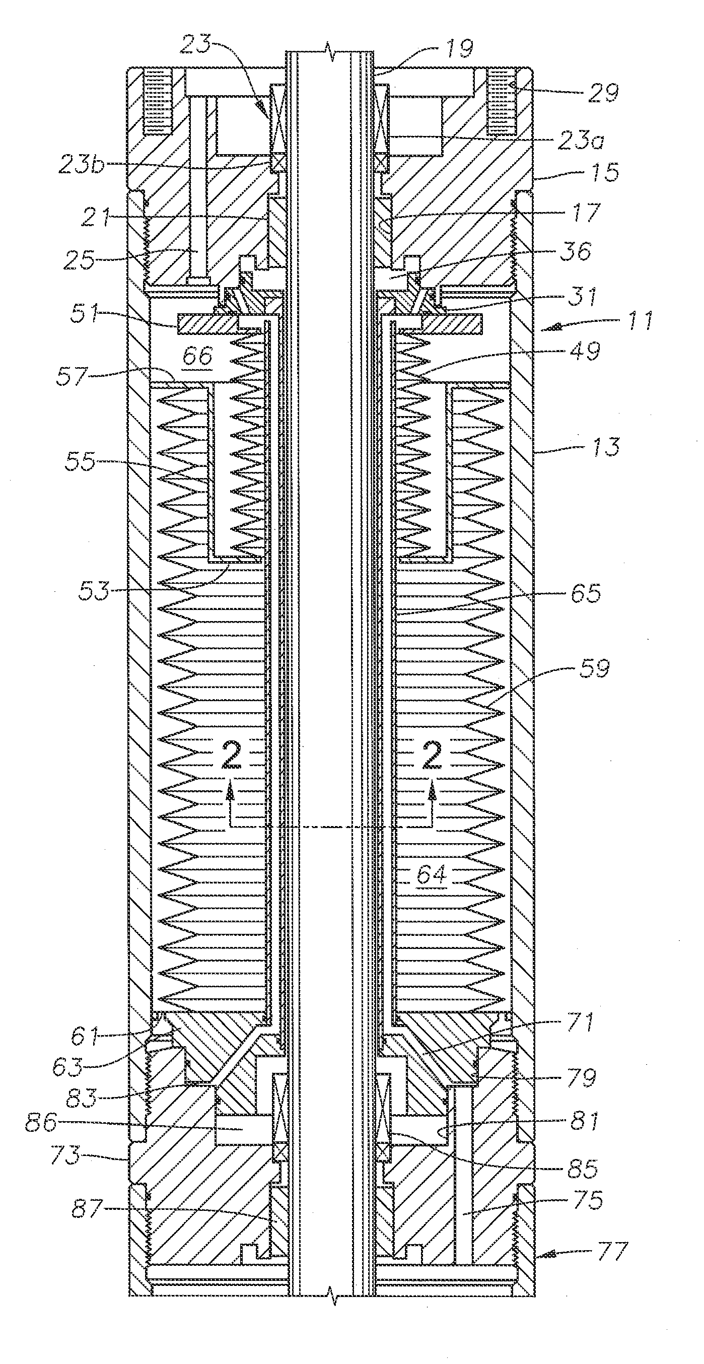
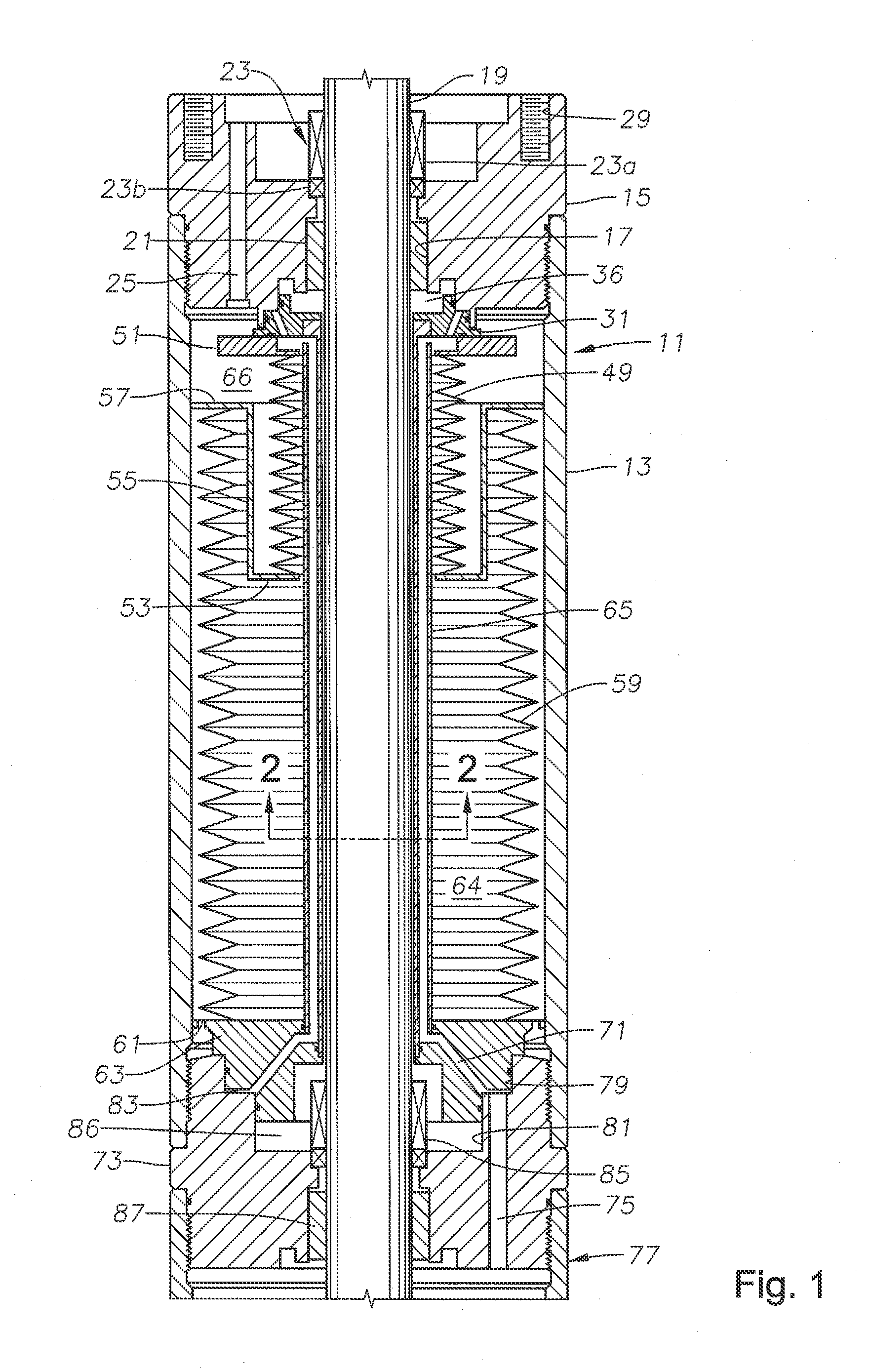
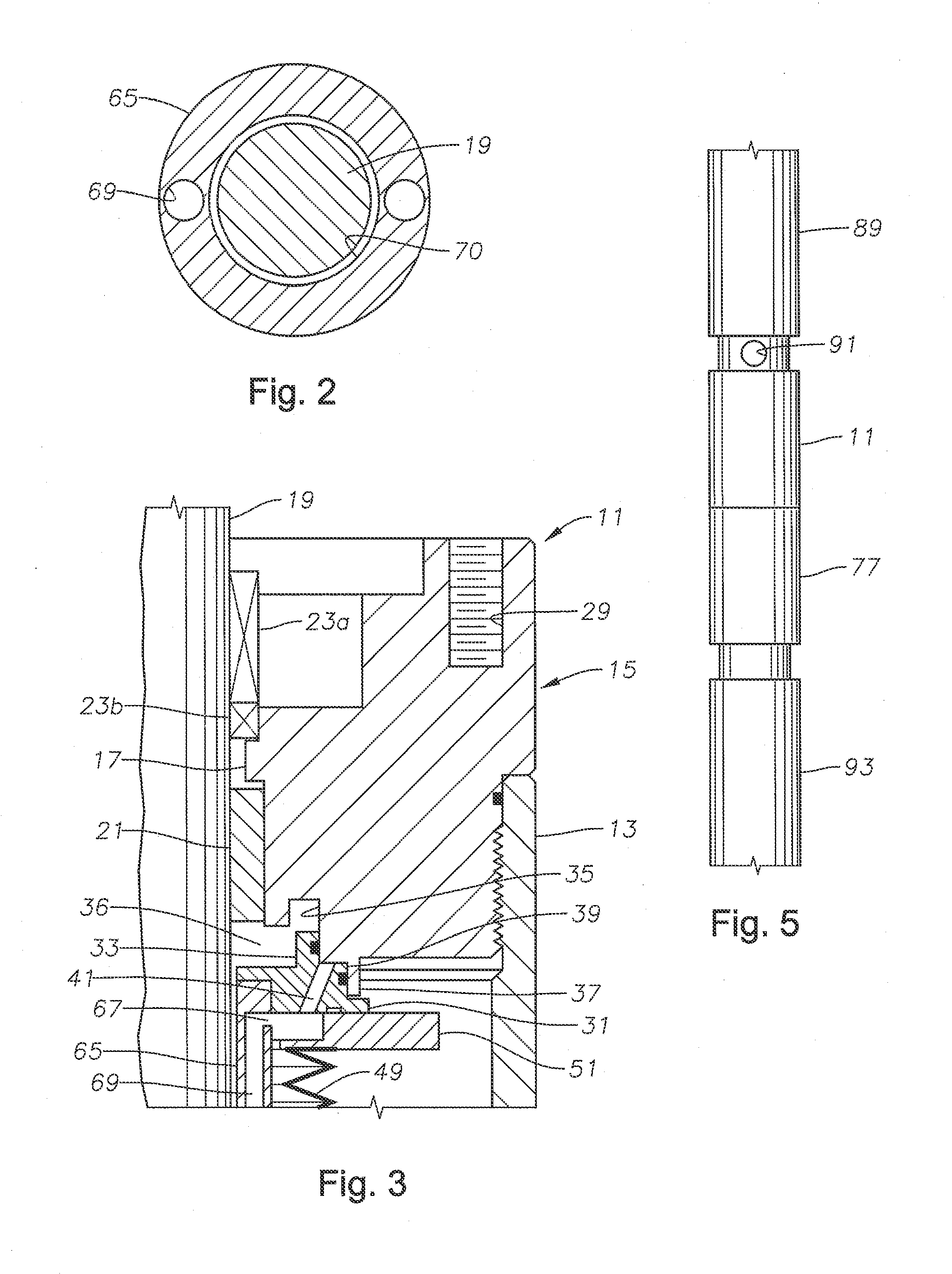
[0018]Referring to FIG. 1, an upper seal section 11, which may also be called a motor protector, has a cylindrical housing 13. An upper adapter 15 secures to threads formed on the inner diameter of housing 13. Upper adapter 15 has a central bore 17 through which a rotatable drive shaft 19 extends. A bushing 21 in bore 17 radially supports shaft 19 but does not form seal around shaft 19. An upper seal 23 is mounted in adapter bore 17 above bushing 21 for sealing around shaft 19. Upper seal 23 is typically a mechanical face seal having a rotating component 23a that rotates with shaft 19 and engages a stationary component 23b sealed to upper adapter 15 in bore 17. Rotating seal component 23a is exposed to wellbore fluid and serves to reduce leakage of wellbore fluid into housing 13.

[0019]Upper adapter 15 has a well fluid passage 25 offset from central bore 17 that admits well fluid to the interior of housing 13. The inlet of well fluid passage 25 is illustrated as being on the upper en...


PUM


Abstract

A submersible well pump assembly has a rotary pump, a motor, and a seal section coupled between the motor and the pump. The seal section has a cylindrical housing having upper and lower adapter and a shaft extending axially through the housing. A guide tube surrounds the shaft and a bellows surrounds the guide tube. A well fluid passage communicates well fluid to a well fluid chamber between the bellows and the housing. A guide tube passage extends axially within the guide tube between an interior and an exterior of the guide tube from an upper portion to a lower portion of the guide tube for communicating lubricant in the motor with lubricant within the bellows.

Description

CROSS-REFERENCE TO RELATED APPLICATION[0001]This application claims priority to provisional application Ser. No. 61 / 502,660 filed Jun. 29, 2011.FIELD OF THE INVENTION[0002]This disclosure relates in general to oil well submersible pumps and in particular to a seal section located between a centrifugal pump and an electric motor, the seal section having a metal bellows.BACKGROUND OF THE INVENTION[0003]Submersible well pump assemblies may be employed in oil and gas wells lacking sufficient pressure to lift liquid well fluids. One type employs a rotary pump driven by a down hole motor. The motor is normally electrical, and the pump may be centrifugal. The motor is filled with a dielectric lubricant to lubricate the bearings and assist in cooling the motor.[0004]A seal section or motor protector is coupled between the pump and the motor. The seal section has a flexible member for reducing a difference between hydrostatic pressure in the well and the lubricant pressure in the motor. The ...

Claims


Application Information

Patent Timeline
IPC IPC(8): F04B39/02
CPCE21B43/128F04D13/10F04C15/0038F04C13/008F04D29/106
Inventor MCKINNEY, KELSEY A.MERRILL, DAN A.
Owner BAKER HUGHES INC
Why Eureka
Try Eureka