
Stand-alone flue gas recirculation fan

Inactive Publication Date: 2013-01-03
FLUOR TECH CORP
View PDF2 Cites 4 Cited by
  • Summary
  • Abstract
  • Description
  • Claims
  • Application Information

AI Technical Summary

Benefits of technology

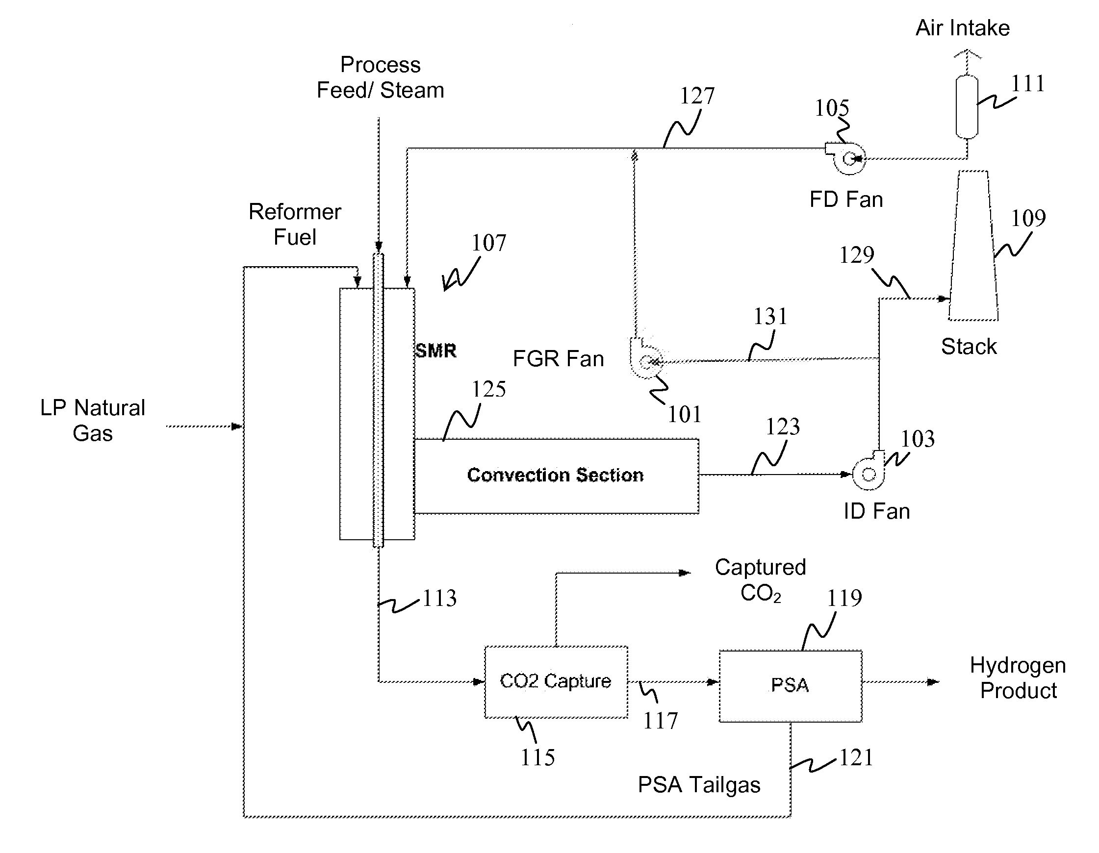
The patent describes a way to reduce the pollutants in a hydrocarbon reformer by using a FGR fan to mix flue gas with air. This is important because the FGR fan lowers the flame temperature in the hydrocarbon reformer, which improves efficiency and reduces emissions. The method is suitable for retrofitting existing hydrocarbon reforming systems and can help to improve the overall performance and environmental impact of these systems.

Problems solved by technology

However, such a configuration would increase the amount of carbon dioxide created, which would need to be recaptured in some manner.
Farmayan, however, provides a rather expensive process since it requires a continuous supply of oxygen to be continuously piped into the reformation chamber and requires the entire reformer pipeline to be reconstructed in order to handle the new oxygen intake valve.
However, the Wood system is undesirable for use with reformers because the introducing of the flue gas upstream of the forced draft fan would likely require modifying existing equipment, which could add significant expense.

Method used


Image

  • Stand-alone flue gas recirculation fan
  • Stand-alone flue gas recirculation fan
  • Stand-alone flue gas recirculation fan

Examples


Embodiment Construction

[0018]One should appreciate that the disclosed techniques provide many advantageous technical effects including reducing the need to modify existing fans while reducing a flame temperature within the hydrocarbon reformer and thereby reducing NOx levels.

[0019]The following discussion provides many example embodiments of the inventive subject matter. Although each embodiment represents a single combination of inventive elements, the inventive subject matter is considered to include all possible combinations of the disclosed elements. Thus if one embodiment comprises elements A, B, and C, and a second embodiment comprises elements B and D, then the inventive subject matter is also considered to include other remaining combinations of A, B, C, or D, even if not explicitly disclosed.

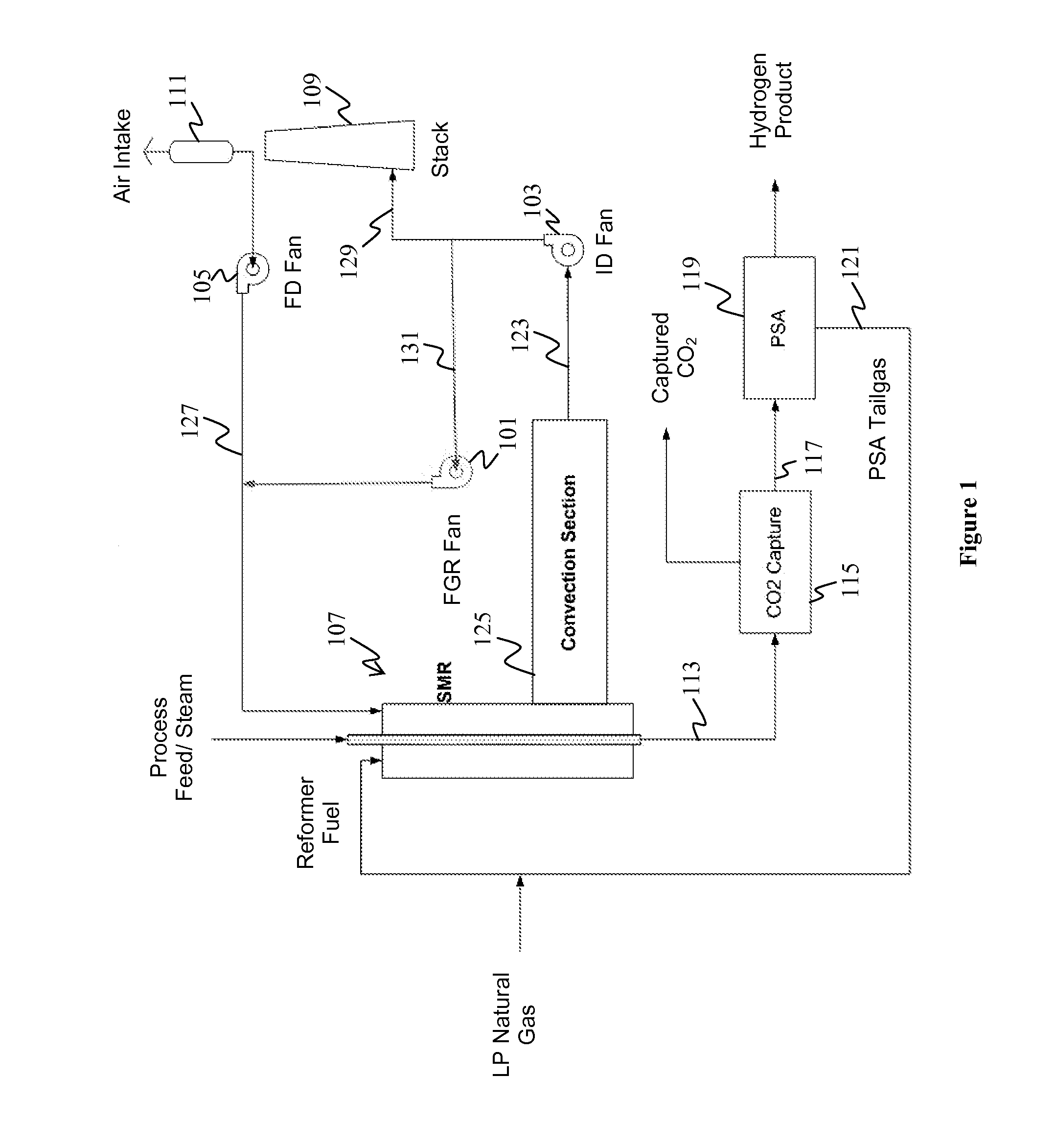
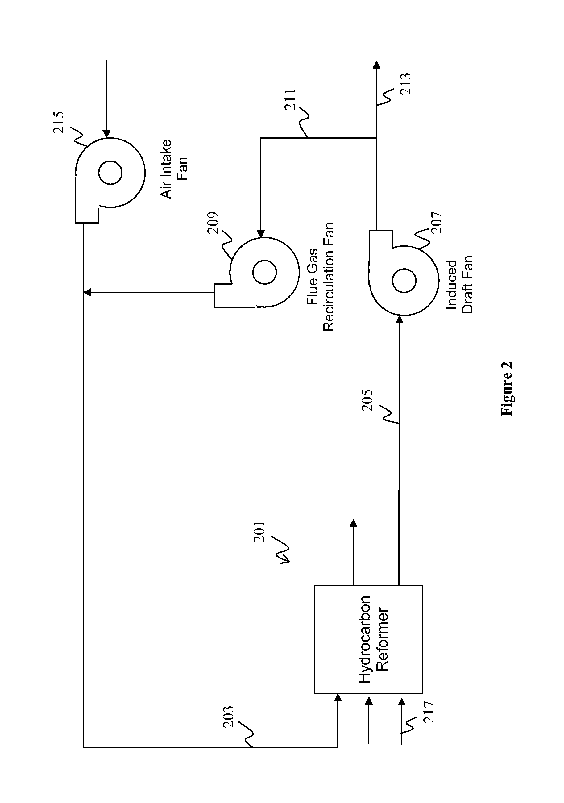
[0020]In FIG. 1, an exemplary embodiment of a system for reducing the formation of pollutants in a hydrocarbon reformer is illustrated. A flue gas recirculation (“FGR”) fan 101 is installed downstream of an i...


PUM

PropertyMeasurementUnit
Pressureaaaaaaaaaa
Concentrationaaaaaaaaaa
Ratioaaaaaaaaaa

Abstract

The formation of pollutants in a hydrocarbon reformer is reduced by use of flue gas recirculation. In typical systems and methods, a hydrocarbon reformer has air intake from an air intake fan where the hydrocarbon reformer produces flue gas exhaust. A portion of the flue gas exhaust is fed into an induced draft fan, wherein a flue gas recirculation (“FGR”) fan draws a portion of the flue gas exhaust located downstream of the induced draft fan. The portion of the flue gas is drawn towards an air intake conduit downstream of the air intake fan, which reduces a flame temperature within the hydrocarbon reformer and reduces the formation of NOx.

Description

[0001]This application claims the benefit of priority to U.S. provisional application having Ser. No. 61 / 503347 filed on Jun. 30, 2011. This and all other extrinsic materials discussed herein are incorporated by reference in their entirety. Where a definition or use of a term in an incorporated reference is inconsistent or contrary to the definition of that term provided herein, the definition of that term provided herein applies and the definition of that term in the reference does not apply.FIELD OF THE INVENTION[0002]The field of the invention is flue gas recirculation by use of a fan.BACKGROUND[0003]The background description includes information that may be useful in understanding the present invention. It is not an admission that any of the information provided herein is prior art or relevant to the presently claimed invention, or that any publication specifically or implicitly referenced is prior art.[0004]It is generally known to reform naturally found hydrocarbons, such as ...

Claims


Application Information

Patent Timeline
IPC IPC(8): B01J10/00B23P11/00B01D29/00
CPCB01D53/047B01D53/1475C01B3/38B01D2256/16B01D2257/504B01J2219/00006Y02C10/06C01B2203/0415C01B2203/043C01B2203/0475C01B2203/0827C01B2203/1241C01B2203/0233Y02C20/40Y02P20/151Y10T137/0402
Inventor STANG, BRENTJOHNSON, PETER H.
Owner FLUOR TECH CORP
Learn More