Drying system for a dishwasher

a drying system and dishwasher technology, applied in the field of dishwashers, can solve the problems of increasing the operation time, consuming more energy, and consuming significant amounts of energy for water heating and drying cycles, and achieves the effects of promoting more turbulence, rapid condensation of water, and fast condensation of moistur

Inactive Publication Date: 2013-01-10
VIKING RANGE
View PDF1 Cites 19 Cited by
  • Summary
  • Abstract
  • Description
  • Claims
  • Application Information

AI Technical Summary

Benefits of technology

[0008]The diffuser is mounted to the lower surface of the passive vent structure body, typically by snap connectors or other similar connectors or fasteners. The diffuser generally includes a series of fins or baffles that define openings therebetween and typically are arranged at varying angles of between approximately 10° to 80° with respect to a vertically aligned central axis extending through the center of the diffuser and vent section of the passive vent structure. It will also be understood that greater or lesser angles of the fins or baffles also can be used, so as to vary the angle(s) at which the airflows are received from the air inlets or vents of the vent section of the passive vent structure and are directed into the wash chamber. As a result, the incoming drying airflows are spread or diffused over a wider area of coverage within the wash chamber, thus promoting more turbulence and faster condensation of moisture and drying of the dishes therein.
[0009]The moisture trap hood is received over the upper surface of the passive vent structure, covering the upper surface and being spaced therefrom. As a result, an airflow opening or inlet is defined / formed at the front end of the passive vent assembly for guiding the incoming drying airflows into the vent section of the passive vent structure. The moisture trap hood further generally helps hold in moist, heated air from the wash chamber of the dishwasher, facilitating more rapid condensation of the water therein, which water is collected and flows back into the air vents to help in the creation or formation of a moisture barrier or substantial seal across the openings of the vents of the passive vent structure.
[0010]During the washing and rinse cycles of a cleaning operation as a higher pressure is maintained within the wash chamber of the dishwasher, the use of the low surface energy plastic or coated materials for the passive vent structure, in combination with the construction of the air vents thereof, facilitates the formation of water beads or bubbles covering the lower vent openings thereof so as to create a substantial moisture seal or barrier across the air vents or inlets. The air vents thus will be effectively sealed against both the ingress of ambient air from outside the dishwasher, as well as the release or escape of hot, moist air or water vapor from inside the wash chamber of the dishwasher.
[0011]Thereafter, during a drying cycle, when the blower of the dishwasher is engaged, and the pressure within the wash chamber is lowered, the water bubbles will be broken or otherwise disturbed, causing the drying airflows to be drawn into and through the air vents of the passive vent assembly and into the wash chamber. As the drying airflows pass through the air vents of the vent section of the passive vent structure, they strike the fins or baffles of the diffuser, which cause the incoming airflows to be diffused and spread out across the wash chamber. The system thus enables the cold air to enter into the wash chamber from the top of the wash chamber through the vent using forced suction created at the bottom of the wash chamber using a blower. Based on the principle that hot air rises, when the drying cycle starts, the hot and moist air in the tub or wash chamber will tend to try to rise and stay at the top and will urge the incoming cold, drier air toward the bottom of the wash chamber. This movement of air will create turbulence of the air flow in the wash chamber, and the diffuser will spread the incoming cold air so that the turbulence of the air flow within the wash chamber in the system generally is further amplified. This creates greater turbulence and a wider flow of air throughout the wash chamber, which can help facilitate the rapid condensation and removal of water and water vapor from the dishes so as to provide enhanced and greater efficiency in the drying cycle for the dishes.

Problems solved by technology

Such water heating and drying cycles typically consume significant amounts of energy necessary to heat the water for washing and rinsing to a temperature sufficient to clean the dishes and to draw a sufficient volume of air through the wash tub of the dishwasher to sufficiently dry the dishes.
Additionally, the drying cycle further often can take a significant amount of time to properly dry the dishes without spotting, which increased operation time requires more energy the longer it runs.

Method used


Image

  • Drying system for a dishwasher
  • Drying system for a dishwasher
  • Drying system for a dishwasher

Examples


Embodiment Construction

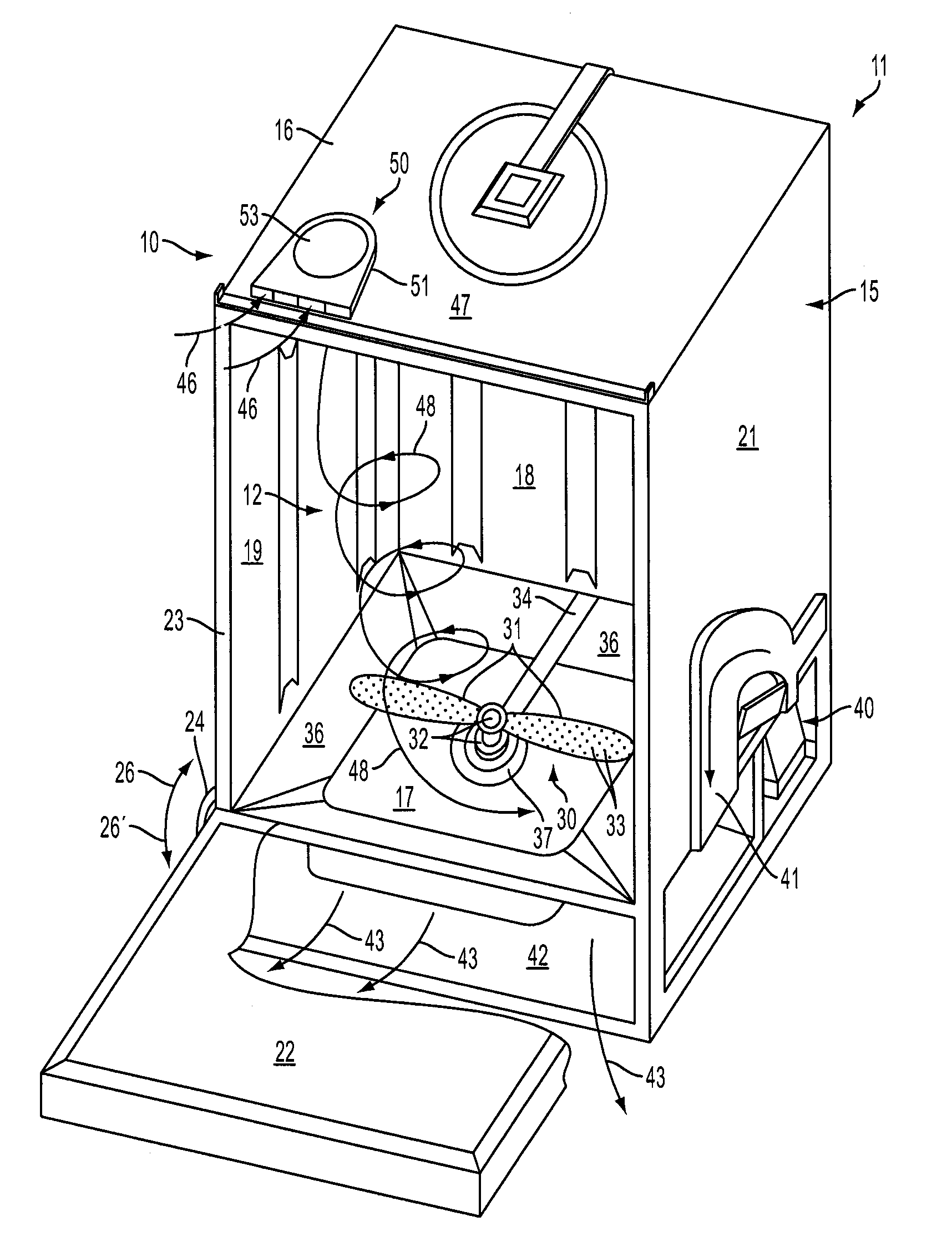
[0020]Referring now to the drawings in which like numerals indicate parts throughout the several views, FIG. 1 generally illustrates a drying system 10 for a dishwasher 11, for facilitating the rapid and efficient drying of dishes within the wash chamber 12 or tub of the dishwasher, without requiring additional power for its operation. The drying system of the present invention is designed to provide enhanced air flow through and across the wash chamber to aid in the rapid drying of dishes therein, while reducing or substantially eliminating flash drying or spotting on the dishes.

[0021]As illustrated in FIG. 1, the dishwasher 11 generally includes a cabinet 15 having a top wall 16, a bottom 17, a rear wall 18, and side walls 19 and 21. The top, bottom, rear and side walls of the cabinet define the open ended wash chamber or tub 12 in which dishes are received, typically on racks (not shown) for cleaning. A door 22 generally is pivotally mounted to the open front side 23 of the dishw...


PUM


Abstract

A drying system for a dishwasher including a passive vent assembly mounted to a top portion of the dishwasher. The passive vent assembly includes a passive vent structure having a series of air vents defined therein and through which drying air flows are drawn into the wash chamber of the dishwasher, a diffuser mounted over the air vents and including a series of fins for spreading the drying air flows across the wash chamber, and a moisture trap hood mounted over an upper surface of the passive vent structure.

Description

FIELD OF THE INVENTION[0001]The present invention generally relates to dishwashers and similar automatic cleaning systems, and in particular to a drying system for a dishwasher, which drying system is designed to facilitate the drying of dishes within the dishwasher in a more efficient manner.BACKGROUND OF THE INVENTION[0002]Dishwashers are a modern convenience in almost every home in the United States and many other countries for washing and cleaning dishes. Modern dishwashers typically have a number of convenience settings or features for scrubbing and cleaning dishes, including heavily soiled dishes, pots and pans, as well as cleaning more delicate dishes and cookware, such as fine china and crystal. Increasingly, as with other household appliances, there is a growing demand to make dishwashers faster and significantly more energy efficient in their operation. During the typical dishwashing cycle, the dishwashers will heat and pump water, generally mixed with a cleaning solution ...

Claims


Application Information

Patent Timeline
Patent Type & Authority Applications(United States)
IPC IPC(8): A47L15/48F26B19/00B08B3/04
CPCA47L15/488A47L15/48A47L15/483A47L15/486
Inventor THAYYULLATHIL, JEMSHEERBROWN, KEVIN
Owner VIKING RANGE
Why Eureka
Try Eureka