
Vascular access catheter

a catheter and vascular technology, applied in the field of vascular access catheters, can solve the problems of significant risks for catheter use, the patient's life-threatening or debilitating thrombosis, and achieve the effects of reducing the risk of infection and clotting episodes, reducing the risk of thrombosis, and reducing the use effect of catheters

Inactive Publication Date: 2007-11-08
HICKMAN ROBERT O +1
View PDF0 Cites 1 Cited by
  • Summary
  • Abstract
  • Description
  • Claims
  • Application Information

AI Technical Summary

Benefits of technology

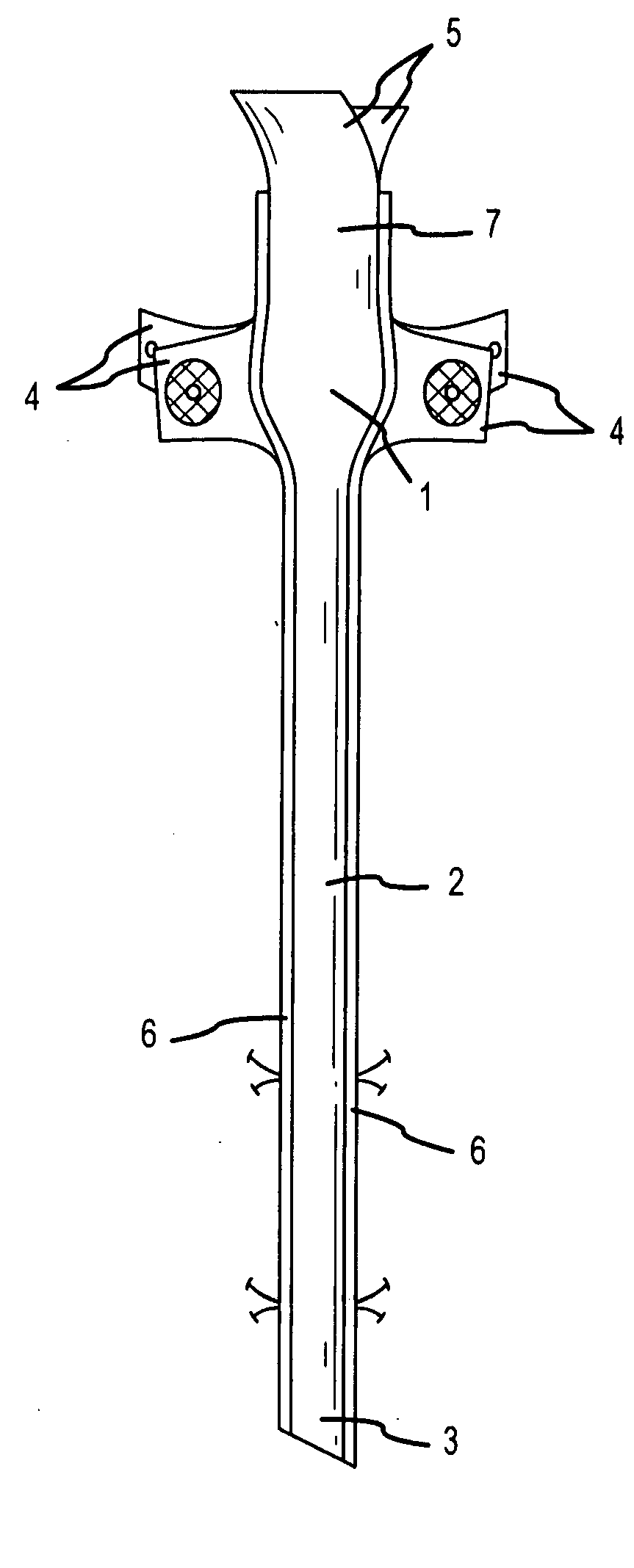
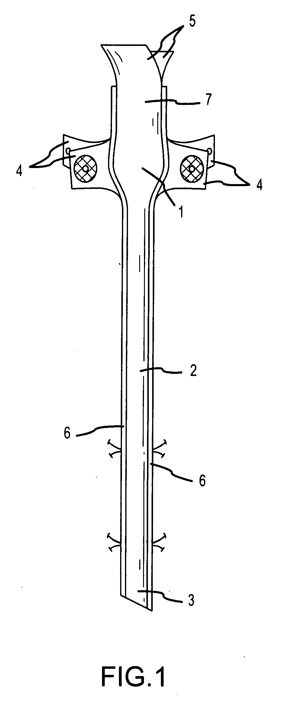
[0014] A catheter in accordance with the present invention will permit rapid deployment, placement, and disposition of the catheter. It should be appreciated that such a catheter will be better tolerated than a conventional catheter. One reason for this is that a catheter in accordance with the present invention is non-occluding due to being constructed from “flat” tubing with a non-inflated total wall thickness in the vein of less than 0.002 inches. This is in contrast to conventional catheters that may have more than fifty times the wall section.
[0015] In addition, another aspect of the present invention is that the lumen may collapse flat when not in use. This is in contrast to conventional catheters that do not collapse flat when not in use. Often catheters that are in-dwelling, are not in use. Thus, when the catheter is not being used may have its lumen collapse flat in accordance with the present invention. In addition, when the lumen collapses, the backflow of blood is better prevented. This collapsing feature may also mean less blood or body fluids in the lumen which will result in less chance of infection, thrombosis, and sepsis. The collapsed profile will not restrict bloodflow as much as a conventional central venous catheter or alternatively create as much turbulence, which is associated with clotting through the vessel.
[0016] In accordance with an another embodiment of the present invention, a catheter in a “Trocar” system would allow for even more rapid deployment as such a catheter would puncture tissue, and the trocar system would be able to guide and deploy the catheter in one step. Only anchoring labor would somewhat mimic conventional cuffed catheters, but here too, the physical size of the catheter, the anchoring flaps, and the exit site would have lower profile than conventional catheters. Optionally, a catheter in accordance with the present invention could be deployed without use of a trocar. That is, the catheter could be deployed using conventional vascular-surgical techniques, at the discretion of a surgeon.
[0017] As the catheter is deployed, it everts as described below and likewise avoids the active transportation of bacteria in the blood.
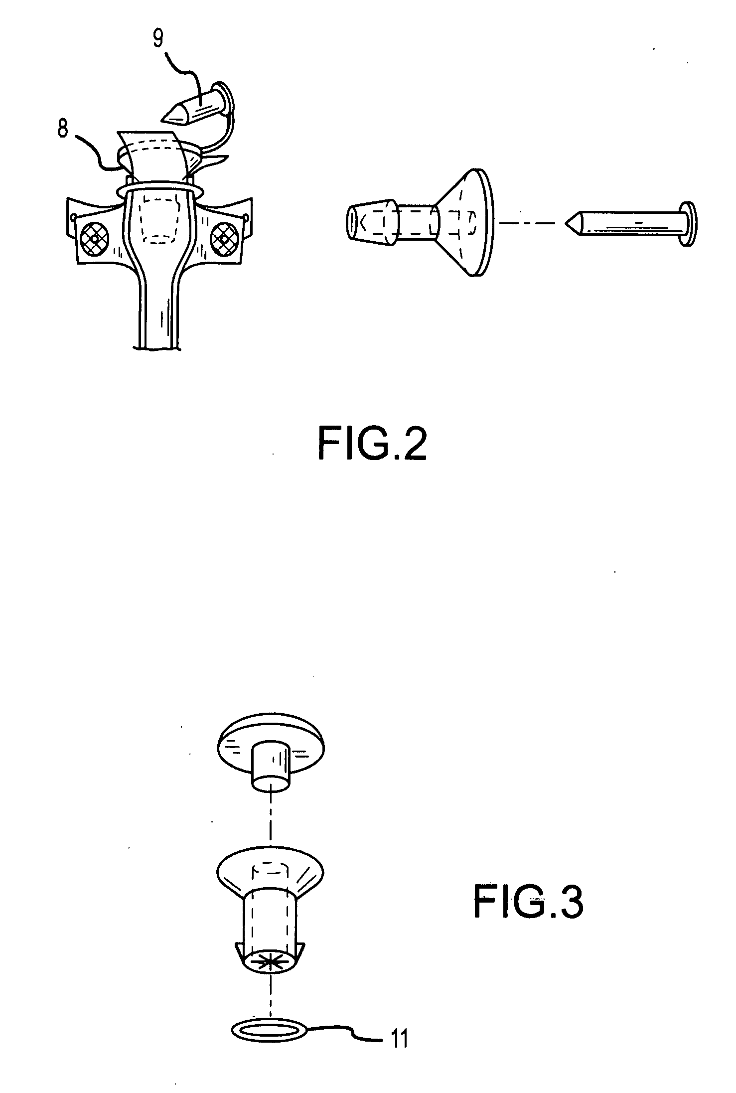
[0018] The proximal end of the catheter may have a hemostatic valve to further control and restrict the backflow of fluids and blood primarily during a therapeutic infusion. In addition, the collapsed lay flat tubing serves to restrict backflow in a manner similar to a “duck-bill” valve. The hemostatic valve of the present invention may be specifically intended for polymer tubing, as opposed to stainless steel needles.

Problems solved by technology

In spite of the improvements made in catheter materials and related areas such as nursing care, catheter care, hospital and doctor office protocols, and with the bonding of drugs (e.g., antibiotics, anti-thrombotic agents), the incidence of infection and clotting episodes, when using catheters, is considerable.
Many of the bouts of infection and thrombosis are life threatening or debilitating to the patient.
However, the incidence of infection and clotting episodes pose significant risks for the use of catheters, especially with patients who are already weakened by other causes.
In addition, conventional central venous in-dwelling catheters may cause thrombosis due to their relative bulk.
In particular, in smaller vessels, occluding caused by catheters will result in a restricted blood flow around the catheter, thus causing thrombosis.

Method used


Image

  • Vascular access catheter
  • Vascular access catheter
  • Vascular access catheter

Examples


Embodiment Construction

[0012] The present invention may be described herein in terms of various hardware components and modules and processing steps. It should be appreciated that such modules and steps may be realized by any number of hardware components configured to perform the specified functions. For example, the present invention may employ various shaped tubes, sheaths, and the like, which may carry out a variety of functions. In addition, those skilled in the art will appreciate that the present invention may be practiced in any number of contexts and that the illustrative embodiment as described herein is merely one exemplary application for the invention. For example, the present invention may be applicable to various types of animals and other applications that require the use of various types of catheters. Further, such general techniques that may be known to those skilled in the art are not described in detail herein.

[0013] A catheter in accordance with the present invention proposes to redu...


PUM


Abstract

An indwelling Fluoropolymer catheter primarily intended for vascular access. The catheter comprises a thin, lubricous sleeve circumferentially folded back over the leading edge of a pusher or positioning tube, affixed to a distal Hemostatic valve / guide assembly. The catheter may, in one embodiment, incorporate a needle or trocar for rapid deployment, which is loaded / positioned from the leading edge, back into the film membrane. The trocar may pierce the skin and advance through body tissues to an artery or vessel. The catheter is then inverted over the pusher tube following the guide of the trocar and optionally a guide wire into the artery. The trocar or needle will be totally withdrawn after catheter placement.

Description

CROSS-REFERENCE TO RELATED APPLICATIONS [0001] This application claims priority to and benefit of U.S. Provisional Application No. 60 / 774,003, entitled “Vascular Access Catheter” and filed on Feb. 15, 2006.FIELD OF INVENTION [0002] The present invention relates generally to vascular access catheters that are intended for long term use. In particular, the present invention relates to vascular access catheters such as those that may be used for dialysis, drug infusion, blood sampling, oncology, nephrology, or the administration of nutrition solutions. BACKGROUND OF THE INVENTION [0003] Typical catheters are fabricated from silicone or urethane elastomer, and are very simple non-everting tubes. The importance of catheters has increased over the years and catheters now play a major role in acute and chronic care. In spite of the improvements made in catheter materials and related areas such as nursing care, catheter care, hospital and doctor office protocols, and with the bonding of dru...

Claims


Application Information

Patent Timeline
IPC IPC(8): A61M31/00
CPCA61M25/0017A61M25/0097A61M2025/0286A61M25/0693A61M2025/0025A61M25/02
Inventor HICKMAN, ROBERT O.JAKER, MARC
Owner HICKMAN ROBERT O
Learn More