Apparatus and Method for Mass Producing Optical Fiber Splice-On Connector Subunits

a technology of optical fiber splice-on connectors and connector subunits, applied in the field of fiber optics, can solve the problems of not being as cost effective for mass termination, not as cost effective as angle cleaved mechanical splice, sc, fc and l

Active Publication Date: 2013-01-10
GOFOTON HLDG
View PDF2 Cites 20 Cited by
  • Summary
  • Abstract
  • Description
  • Claims
  • Application Information

AI Technical Summary

Benefits of technology

[0015]After the magazine is filled with the subunits, the magazine is mounted on the frame and moved on the frame to orient a slot containing a subunit within the cleaving zone. At this point, the cleaver is engaged to cut the tip of the first portion of the fiber stub contained within the subunit. The cleaver is then disengaged from the first portion. The fiber holder is engaged to the second portion (either before or after the cleaving process) to grasp the second portion of the fiber stub. The fiber holder is then moved along the track away from the cleaver, without changing the radial orientation of the fiber stub within the subunit, until the first portion of the fiber stub has a specified length, and the moved fiber drags epoxy along and fully filled within the ferrule for curing. The fiber holder is then disengaged from the second portion. These steps of cleaving and pulling the fiber stub contained within each subunit are repeated for each slot containing a subunit in the magazine, until they have all been completed.
[0016]The magazine is then detached from the frame and placed in an oven to cure the epoxy within the subunits. Thereafter, the magazine is removed from the oven and allowed to cool. The keying portion of each subunit is then disengaged from the locking portion of the slot to remove each subunit from the magazine and provide a plurality of subunits, each having the fiber stub disposed at a fixed radial orientation therein and having a first portion with a specified length ending at the cleaved tip. The second portion is then cut and the juncture and with the ferrule and the exposed end is polished (into an APC) so that it may be connected with a ferrule in another factory made APC connector.

Problems solved by technology

There are many field fusion splicer available, but are not really cost effective for mass terminations.
Fusion splice-on factory pre-made connector is in use for many years, however it is not as cost effective as angle cleaved mechanical splice-on (SC, FC, LC)—APC connector.

Method used


Image

  • Apparatus and Method for Mass Producing Optical Fiber Splice-On Connector Subunits
  • Apparatus and Method for Mass Producing Optical Fiber Splice-On Connector Subunits
  • Apparatus and Method for Mass Producing Optical Fiber Splice-On Connector Subunits

Examples


Embodiment Construction

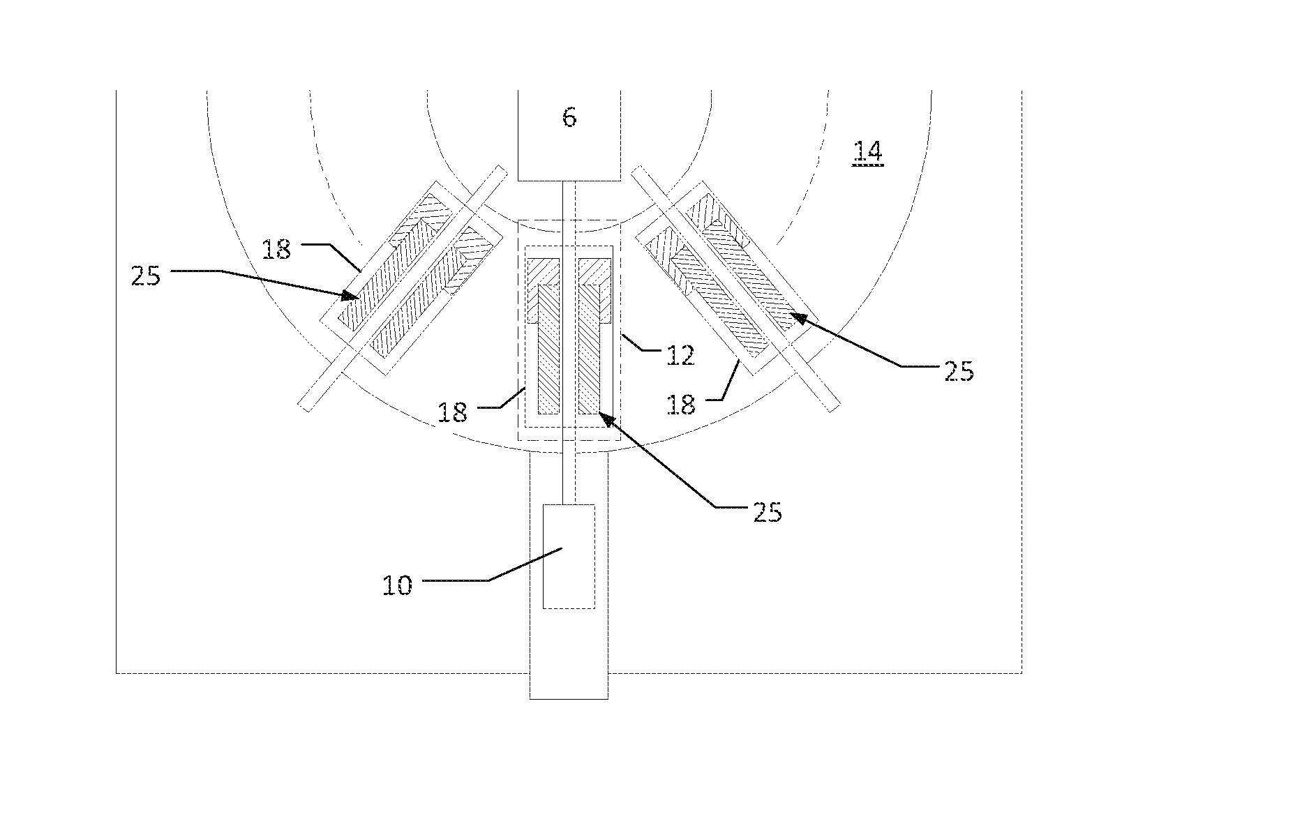
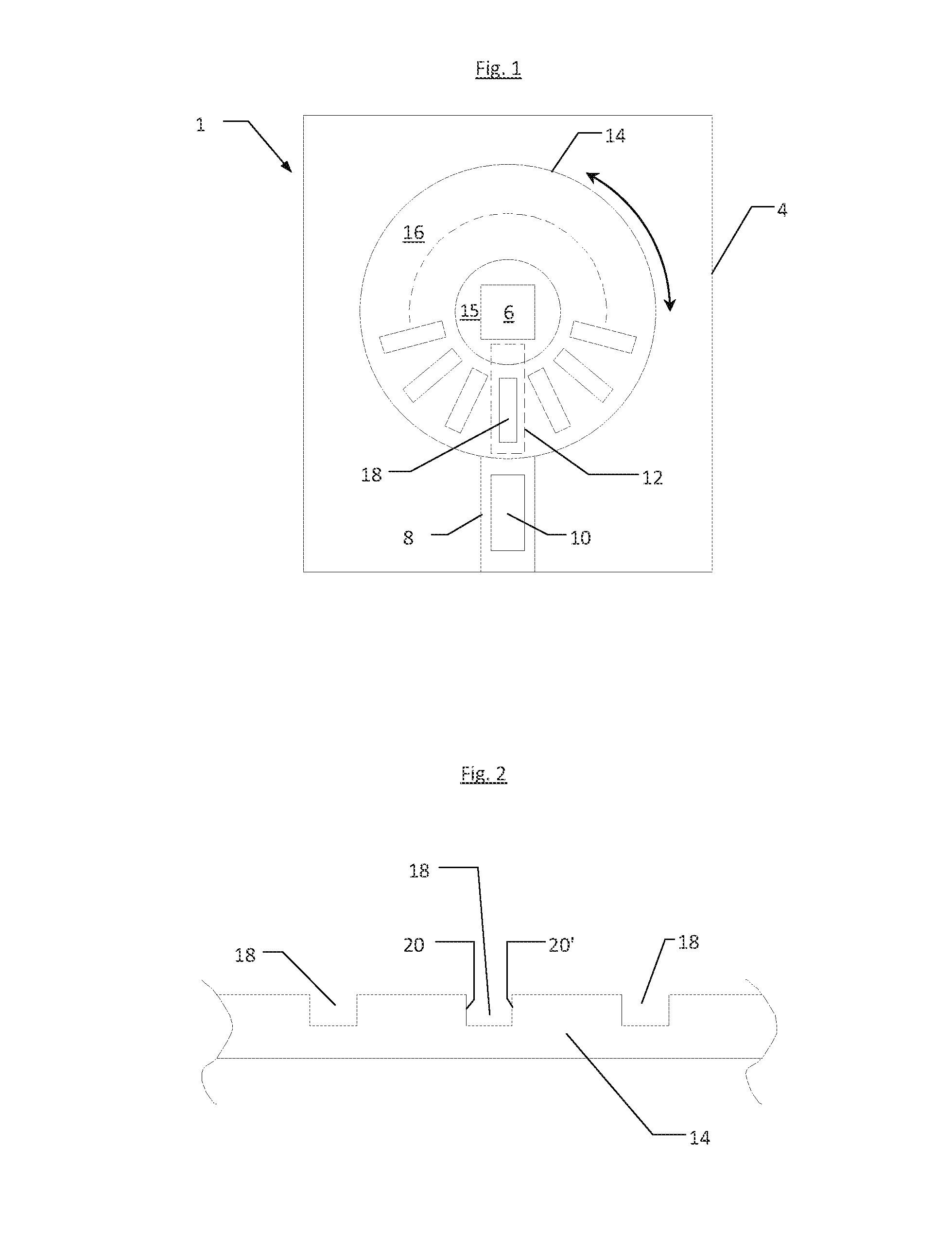
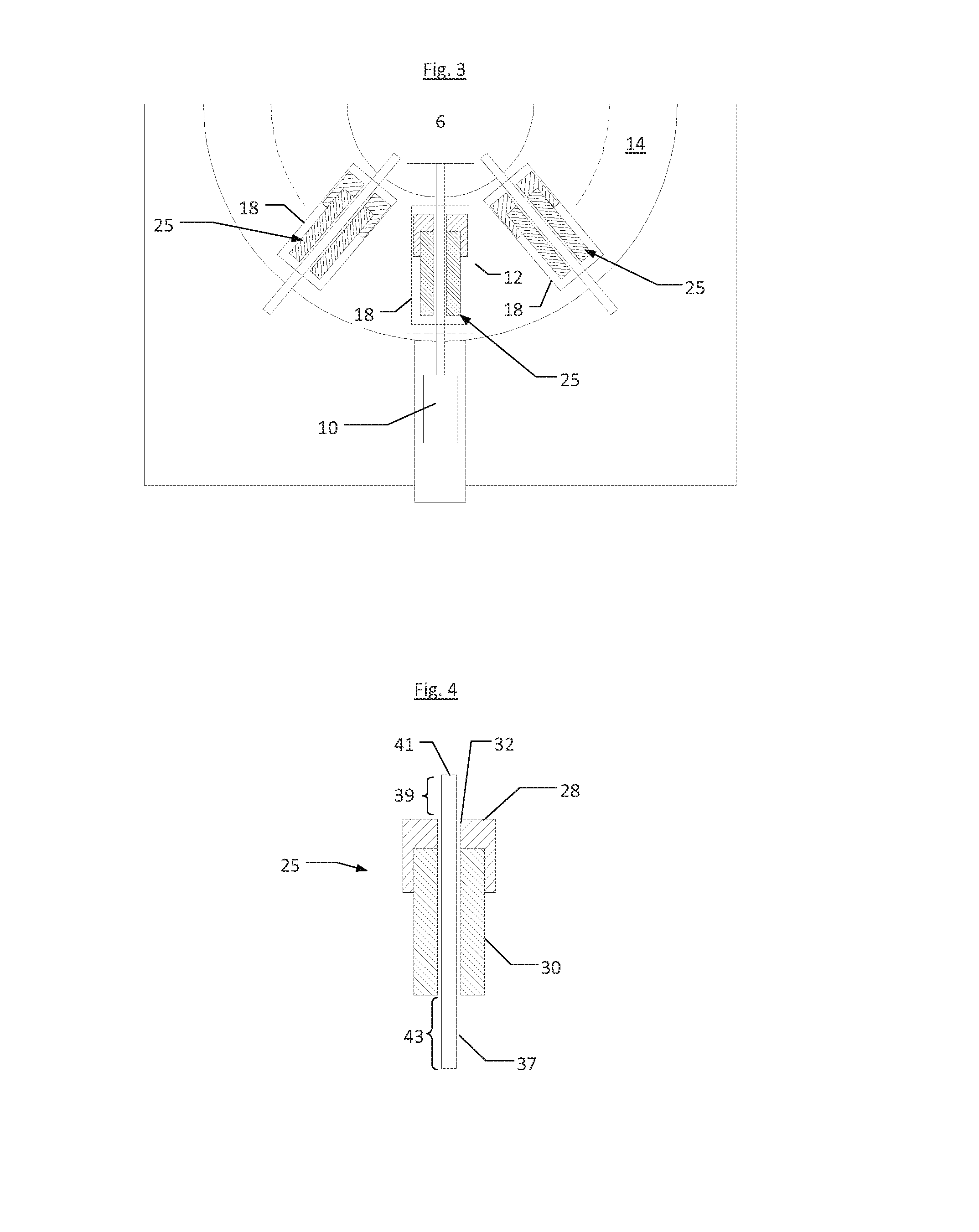
[0036]The invention will first be described by reference to its structure and thereafter further described by reference the method of carrying out the invention. FIG. 1 shows a first preferred embodiment of the invention. Referring to FIG. 1, the invention provides an apparatus 1 for mass producing a plurality of fiber optic mechanical splice-on connector subunits. The apparatus 1 is supported by a frame 4. A cleaver 6 is mounted on the frame. The cleaver 6 is preferably a flat edge angled cleaver (for example, made by IL Sintech Co. Ltd.) that is capable of cleaving the tip of a fiber stub with an angled flat edge. The particular angle used is typically 8° although other angles may be employed. A track 8 is mounted on the frame 4 in alignment with the cleaver 6. A fiber holder 10 is slidably mounted on the track 8. The fiber holder 10 is slidably movable toward and away from the cleaver 6. The area between the cleaver 6 and the fiber holder 10 defines a cleaving zone 12.

[0037]A mag...


PUM

PropertyMeasurementUnit
anglesaaaaaaaaaa
massaaaaaaaaaa
areaaaaaaaaaaa

Abstract

The invention provides and apparatus and method for mass producing a plurality of fiber optic mechanical splice-on connector subunits. The apparatus utilizes a magazine detachably mounted on a frame and containing a plurality of slots. The slots contain a plurality of subunits, each of which includes a ferrule assembly carrying a fiber stub coated in uncured epoxy. The slots are moved through a cleaving zone on the apparatus defined by the area between a cleaver and fiber holder, wherein the fiber stubs are cleaved and then pulled so the portion of the fiber stub extending from the ferrule assembly to the cleaved end has a specified length. After cleaving and pulling all the fiber stubs in the magazine, the magazine is detached from the apparatus and moved to an oven wherein the epoxy is cured. After cooling, the subunits and removed from the magazine to provide a plurality of subunits, each containing a cleaved fiber stub securely oriented therein.

Description

FIELD OF THE INVENTION [0001]The present invention relates to the field of fiber optics, particularly angle cleaved mechanical splice-on (SC. FC and LC) angled physical contact (“APC”) connectors. In particular, the invention concerns an apparatus and method for mass producing subunits used in the manufacture of mechanical splice-on (SC, FC and LC)—APC connectors in the industry. The apparatus and method facilitate mass production of subunits that precisely control the orientation of the fiber stub contained therein and the length of the fiber stub portion extending from the subunit to the cleaved tip.BACKGROUND OF THE INVENTION[0002]In the fiber optics communication industry, optical fibers are used in a growing number of ways, particularly out in the field in residential and commercial structures. There is an ever-increasing need to provide better ways of connecting optical fibers so that insertion and return losses are controlled and optimized. Fusion splicing yields connections ...

Claims


Application Information

Patent Timeline
Patent Type & Authority Applications(United States)
IPC IPC(8): G02B6/25B32B38/10B32B37/12B32B37/14B32B37/02B32B37/06
CPCG02B6/3846G02B6/3851Y10T156/1052G02B6/3898G02B6/3863Y10T225/371
Inventor TAKEUCHI, KENICHIROLU, HAIGUANG
Owner GOFOTON HLDG
Why Eureka
Try Eureka