Disk Brake And Production Method For A Disk Brake

Active Publication Date: 2013-01-10
HALDEX BRAKE PROD AB
View PDF10 Cites 59 Cited by
  • Summary
  • Abstract
  • Description
  • Claims
  • Application Information

AI Technical Summary

Benefits of technology

[0013]Thus, it is an object of the present invention to provide a brake mechanism which gets by with less components as compared to the prior art and which comprises a less complex structure. Associated therewith the

Problems solved by technology

The adjustment device provided for that and the force amplification mechanism in the form of a roller-ramp-mechanism to be used therewith comprise a plurality of single components which render the assembly process to be complicated and thus expensive.
Moreover, in connection with the assembly the brake caliper to be employed in such a disc brake has to be provided with plenty of openings, both on the rear side of the housing of the brake caliper and on the side facing the brake disc, which, however, are associated with major sealing problems.
Indeed, this brake mechanism is less complex than the one as mentioned above, however, its assembly in the housing of the brake caliper proves to be cumbersome and thus time-consuming, since during the assembly inside of the housing a rotatable connection between a thrust piece and the lever by means of a roller element to be arranged between these components has to be developed and maintained.
Moreover, the brake mechanism as realized in such a way can be inserted via the rear side of the brake caliper only, which necessitates a relatively large opening in the rear section of the housing of the brake caliper or even a two-piece caliper comprising a joint gap, whereby necess

Method used


Image

  • Disk Brake And Production Method For A Disk Brake
  • Disk Brake And Production Method For A Disk Brake
  • Disk Brake And Production Method For A Disk Brake

Examples


Embodiment Construction

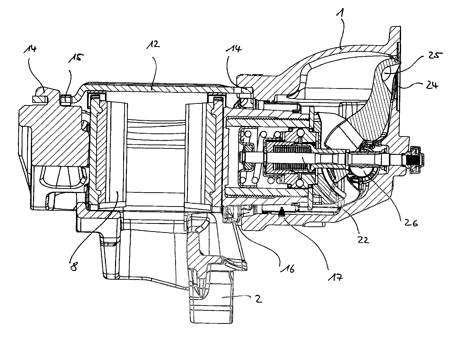
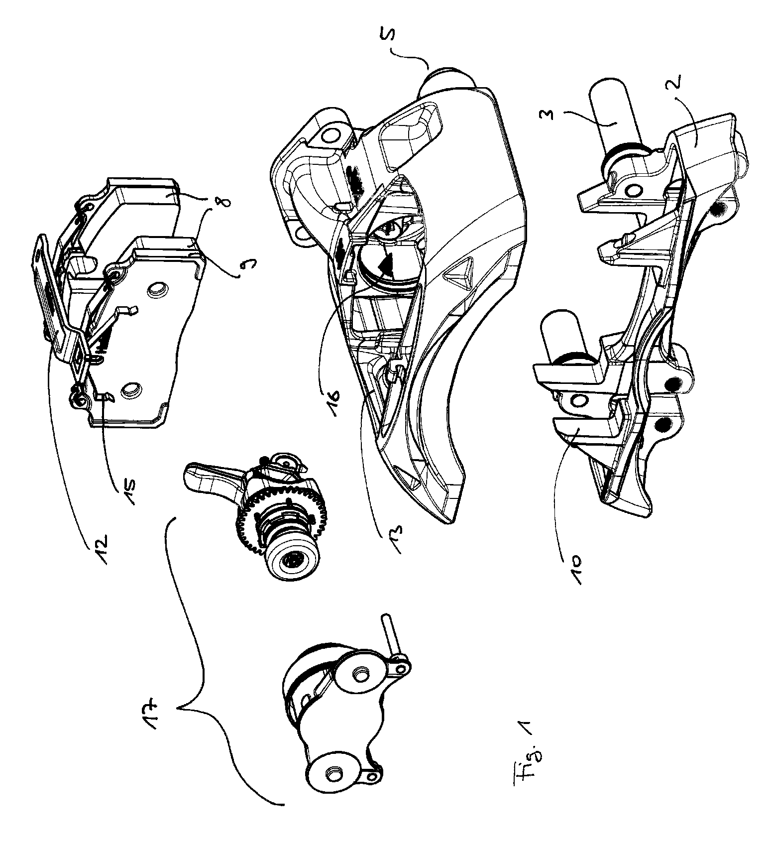
[0144]FIG. 1 shows the disc brake according to the invention in explosive view with its substantial components, which are shown in their assembled state in FIG. 2 and FIG. 3, respectively.

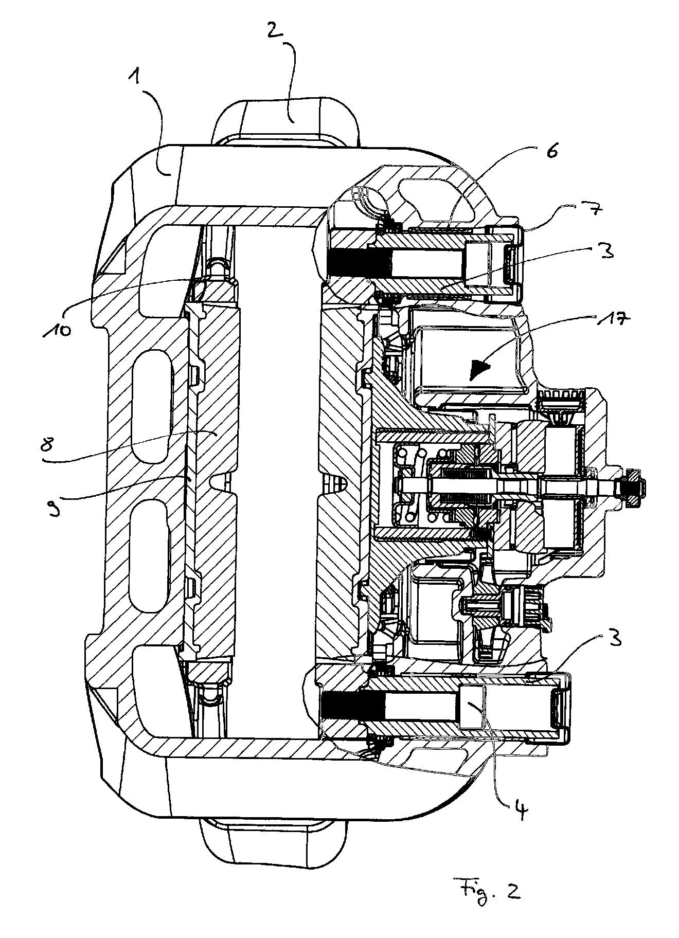
[0145]The disc brake comprises a brake caliper 1 which is slideably guided on a carrier 2. For that purpose the brake caliper 1 is guided on the carrier 2 by means of slide bearings 3.

[0146]The slide bearings 3 are fixed to the carrier 2 by means of bolts 4 and received in openings 5 in the housing of the brake caliper 1, correspondingly. Elastic slide bearing elements 6 are provided between the slide bearing 3 and the inner wall of the openings 5, as this, for example, has been explained in the German Utility Model no. 20 2008 006 779 of the applicant.

[0147]In order to ensure a proper functioning of the slide bearing mechanism made in such a way, the openings 5 in the brake caliper 1 are sealingly closed to the outside by means of end caps 7, as these, for example, have been explained in the Germa...


PUM

PropertyMeasurementUnit
Forceaaaaaaaaaa
Frictionaaaaaaaaaa
Displacementaaaaaaaaaa

Abstract

A disk brake having a brake caliper and a brake actuation mechanism being supported in it, in which the brake actuation mechanism includes an amplification mechanism for introducing a clamping force, an adjustment device for compensation of lining wear with a torque clutch, a thrust element for transmitting the clamping force onto a brake disc and a reset device, which components are arranged around a rod, in which the torque clutch, for example, is formed as a roller-ramp-mechanism. A spring force can act onto the torque clutch by means of the reset device thereby forming a torque limit. Furthermore the invention relates to an assembly method for such a disc brake.

Description

CROSS-REFERENCE TO RELATED APPLICATIONS[0001]The present application is a continuation of pending International Patent Application PCT / EP2011 / 001209 filed on Mar. 11, 2011 which designates the United States and claims priority from German Application 10 2010 011 725.0 filed on Mar. 17, 2010, the content of which is incorporated herein by reference.FIELD OF THE INVENTION[0002]The present invention relates to a disc brake, in particular for an utility vehicle, and to a method for manufacturing and assembly, respectively, of such a disc brake.[0003]In this connection the invention shall include disc brakes which either comprise a sliding caliper or a fixed caliper, which overlap one or more brake discs. Mainly but not exclusively the invention relates to disc brakes with lining sections.BACKGROUND OF THE INVENTION[0004]Disc brakes, in particular for heavy load trucks, are known with different configurations, both with respect to the type of the actuation mechanism, with respect to the ...

Claims


Application Information

Patent Timeline
IPC IPC(8): B60T1/06B60T17/22B23P11/00F16D65/40
CPCF16D55/227F16D65/18F16D65/567F16D66/026Y10T29/49863F16D2125/28F16D2250/0084F16D65/0043Y10T29/49826F16D2121/14
Inventor SANDBERG, STEFANWELIN, HANS
Owner HALDEX BRAKE PROD AB
Why Eureka
Try Eureka