Machine and method for winding reels of web material

Inactive Publication Date: 2013-01-10
A CELLI PAPER
View PDF3 Cites 8 Cited by
  • Summary
  • Abstract
  • Description
  • Claims
  • Application Information

AI Technical Summary

Benefits of technology

[0013]The object of the present invention is to provide a new rewinding machine and a new winding method that overcome, wholly or partially, one or more drawbacks of the known machines.
[0014]According to one aspect, the invention relates to a rewinding machine comprising: a first winding member and a second winding member defining a winding cradle; a winding rod inserter for introducing a winding rod in the winding cradle and for winding a reel of web material on said winding rod, as well as a system of roller(s) suitable to control the reel diameter increase. The inserter is advantageously arranged and designed so as to introduce the winding rod against the first winding member towards the winding cradle; and the second winding member is designed and arranged to allow a previously formed reel to be stopped and unloaded from said winding cradle. In this way, while a formed reel is unloaded from the winding cradle, a new winding rod is inserted towards the winding cradle and starts to wind around itself a second reel of web material as a result of the contact with only one of the two winding members. The two winding members can be thus controlled independently of each other, the first one to start winding a new reel and the second one to stop and unload a reel that has been completed during the previous winding cycle. The cycle of unloading the reel and starting winding a new reel is therefore faster and can be performed without stopping the machine. The feed speed of the web material is preferably reduced during the reel unloading, but it is not stopped. The speed reduction is substantially lower than the reduction necessary in other known rewinding machines, with consequent advantages from a productivity viewpoint too.
[0027]The speed of the winding members can change from a steady-state speed, or winding speed, to an exchange speed or replacement speed, at which the reel being completed moves away from the first winding member towards an exchange area. The second winding member can be controlled so as further to slow down from the exchange or replacement speed to a reduced speed, at which the reel being completed is brought. This reduced speed is lower than the exchange speed. When the reel rotates at a reduced peripheral speed, lower than the exchange speed, at which the web material is temporally fed, a loop can be formed, which facilitates the step of severing the web material and starting winding a new reel on a new winding rod.
[0049]moving said first reel of web material away from said first winding roller maintaining it into rotation through at least said second winding roller and said fourth winding roller and reducing the rotation speed of the reel from a winding speed to a replacement speed, lower than the winding speed;
[0057]In some embodiments of the method according to the invention it is provided that the rotation speed of the first reel is reduced by slowing down the second winding roller, the third winding roller and the fourth winding roller; that the third winding roller and the fourth winding roller are moved away from the first reel; said third winding roller and said fourth winding roller are accelerated until the winding speed and said second winding rod and the reel being formed around it are engaged with said third winding roller and said fourth winding roller.
[0058]In some embodiments the winding method provides the steps of: forming a loop of web material between said first reel and said second winding rod slowing down the rotation speed of said first reel; and of holding said loop of web material between said second winding rod and said first winding member and causing the severing of the web material between said first reel and said second winding rod.

Problems solved by technology

These start and stop cycles entail production losses as well as stresses in the production line.

Method used


Image

  • Machine and method for winding reels of web material
  • Machine and method for winding reels of web material
  • Machine and method for winding reels of web material

Examples


Embodiment Construction

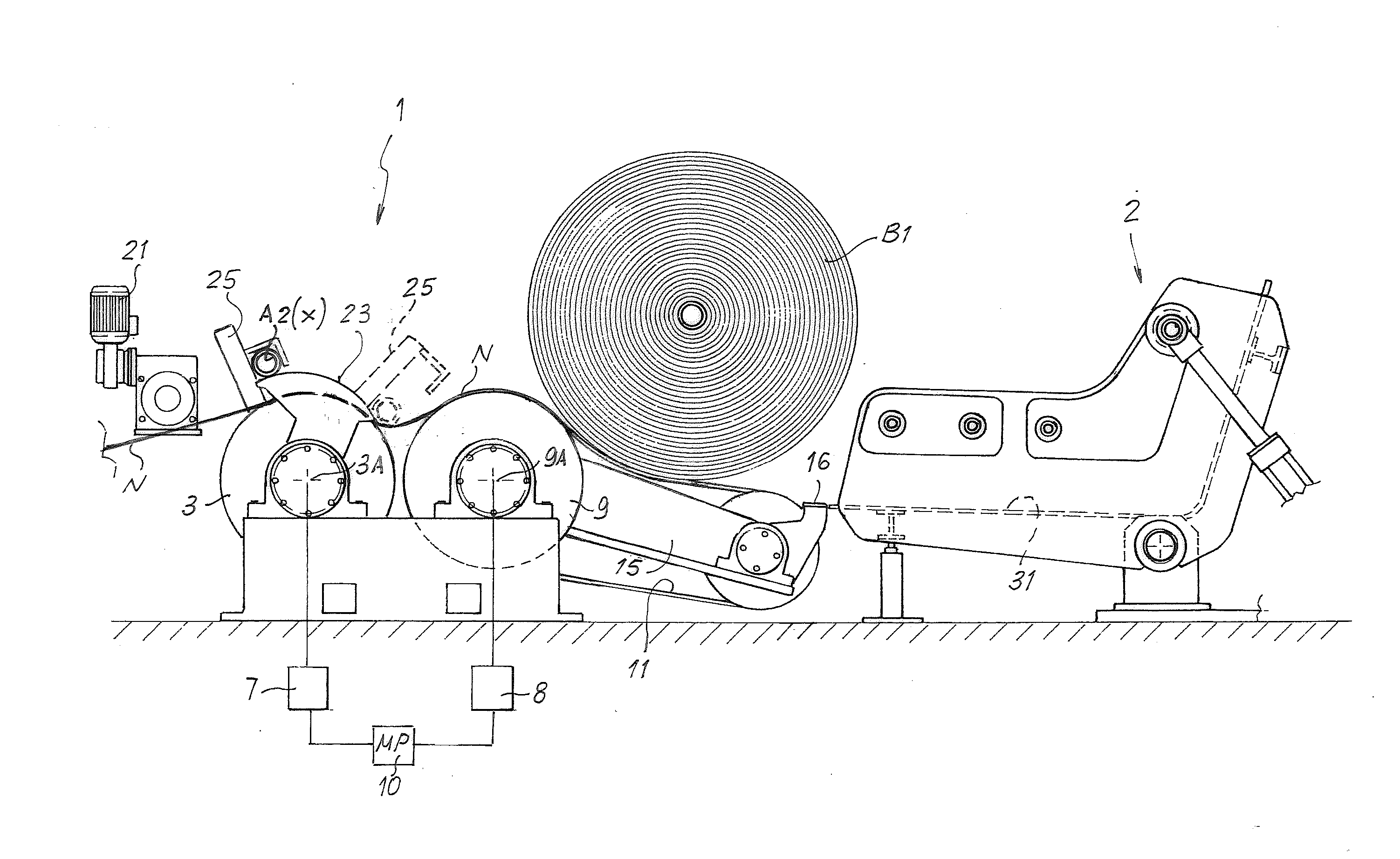
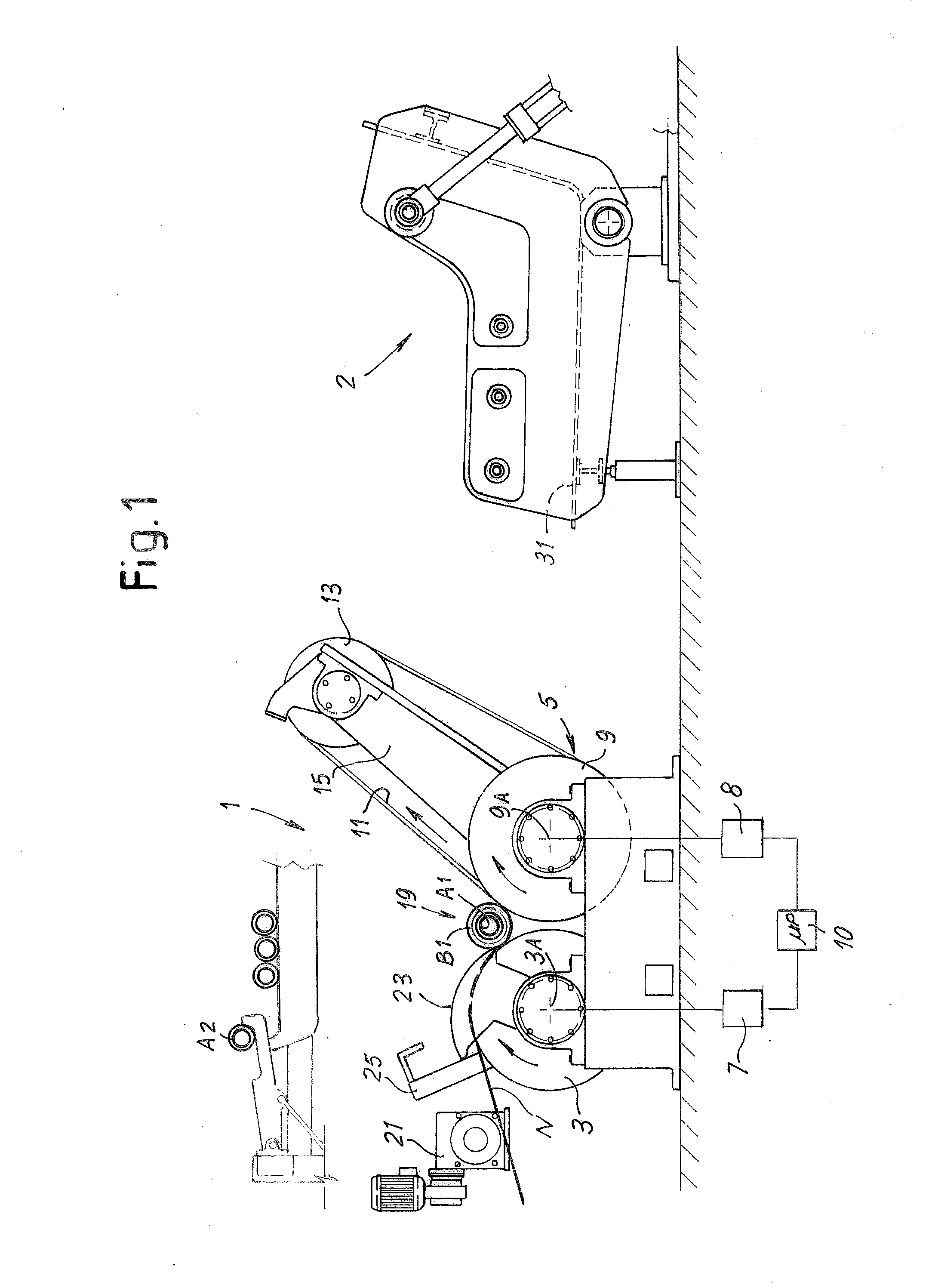
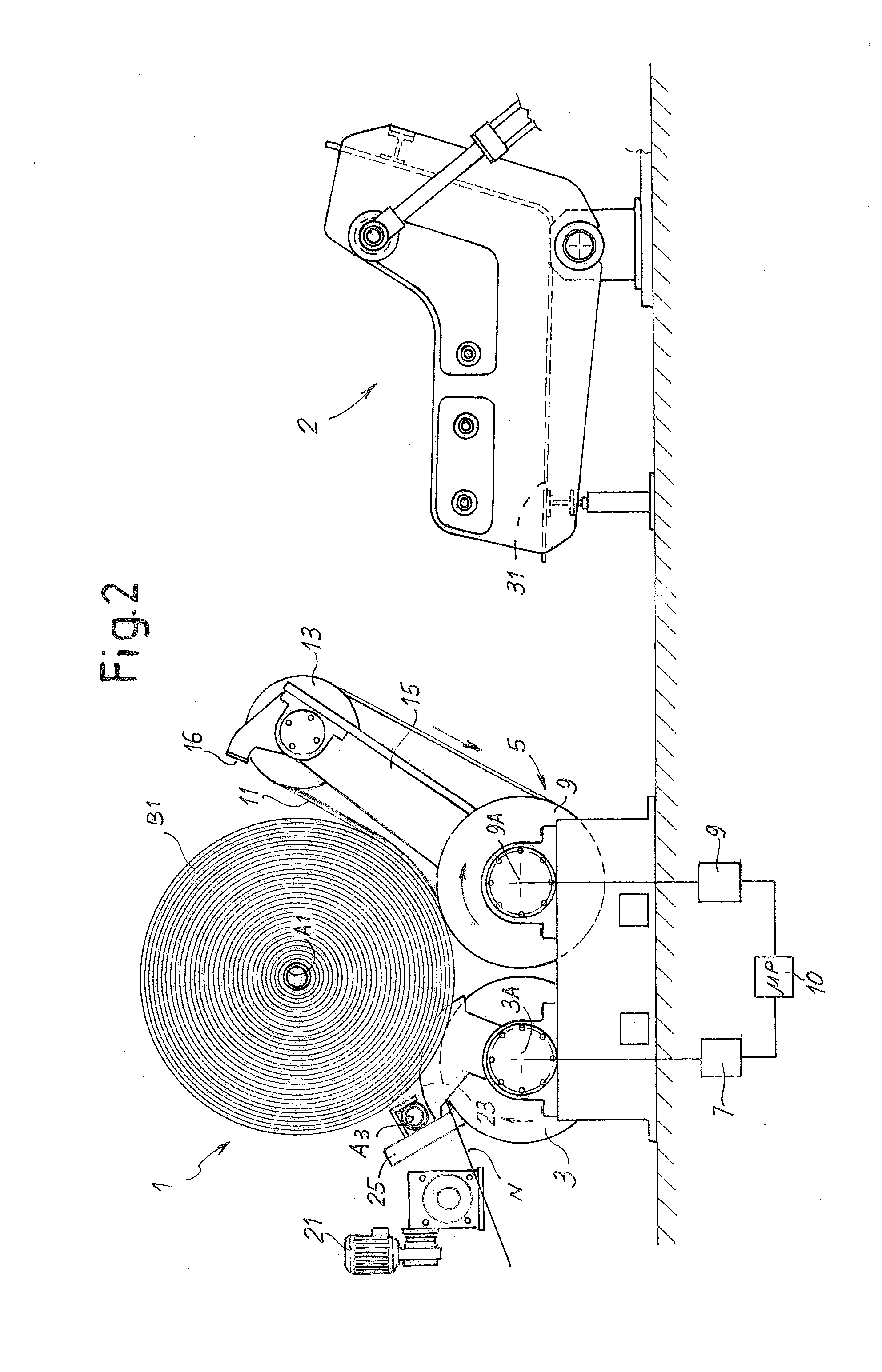
[0067]The rewinding machine, indicated in its entirety with number 1, comprises a first winding member 3 and a second winding member 5. In some embodiments the first winding member 3 is constituted by, or comprised of, a winding roller rotating around a substantially horizontal axis 3A. The rotation of the roller is controlled by an electric motor, schematically indicated with number 7.

[0068]In some embodiments, the second winding member 5 comprises a second winding roller 9 rotating around a substantially horizontal axis 9A substantially parallel to the axis 3A of the winding roller 3. The winding rollers 3 and 9 form a nip therebetween and define a winding cradle.

[0069]In some embodiments the winding roller 9 is driven into rotation by a second motor 8, distinct from the motor 7. The motors 7 and 8 are preferably connected to a central control unit 10, with which also the other members of the machine are interfaced to perform the winding cycle described below. The control unit 10 ...


PUM

PropertyMeasurementUnit
rotation speedaaaaaaaaaa
speedaaaaaaaaaa
speedaaaaaaaaaa

Abstract

The rewinding machine comprises: a first winding member (3) and a second winding member (9) defining a winding cradle (19); a winding rod inserter (25) for introducing a winding rod (A1; A2) in the winding cradle (19) to wind a reel (B1) of web material (N) on said winding rod. The inserter (25) is arranged and designed for introducing the winding rod (A2) against the first winding member (3) towards the winding cradle (19) and the second winding member (5) is designed and arranged to allow a previously formed reel (B1) to be unloaded from the winding cradle (19).

Description

TECHNICAL FIELD [0001]The present invention relates to winding or rewinding machines for producing rolls or reels of web material, such as paper, tissue paper, non-woven fabric and the like. The invention also relates to improvements to the winding methods for producing rolls or reels of web material.STATE OF THE ART [0002]In the paper converting industry and in other continuous web material processing industries there is the need for producing reels or rolls of wound web material constituting intermediate products for subsequent converting operations. In the paper converting field, in particular, it is provided for a single or multiple ply of cellulosic material, for example tissue paper, to be unwound and wound again on reels. For producing large diameter reels, designed to be subsequently unwound and rewound in small diameter logs that, cut orthogonally to their axis, producing single rolls for final consumption, start-stop rewinding machines are used, i.e. machines wherein the f...

Claims


Application Information

Patent Timeline
Patent Type & Authority Applications(United States)
IPC IPC(8): B65H19/22
CPCB65H19/2246B65H2301/414866B65H2301/41447B65H2701/1924
Inventor LANGELLA, DANIELE
Owner A CELLI PAPER
Why Eureka
Try Eureka