Power mosfet with integrated gate resistor and diode-connected mosfet

a technology of power mosfet and gate resistor, which is applied in the field of power transistors, can solve the problems of reducing the efficiency of buck converters containing power transistors, power transistors in switching circuits may experience ringing, etc., and achieve the effect of reducing the efficiency of buck converters

Active Publication Date: 2013-01-10
TEXAS INSTR INC
View PDF3 Cites 39 Cited by
  • Summary
  • Abstract
  • Description
  • Claims
  • Application Information

AI Technical Summary

Benefits of technology

[0004]Power transistors in switching circuits may experience ringing when the power transistor is turned on and off. Snubbing components which desirably limit the ringing may undesirably reduce efficiency of buck converters containing the power transistors.

Problems solved by technology

Power transistors in switching circuits may experience ringing when the power transistor is turned on and off.
Snubbing components which desirably limit the ringing may undesirably reduce efficiency of buck converters containing the power transistors.

Method used


Image

  • Power mosfet with integrated gate resistor and diode-connected mosfet
  • Power mosfet with integrated gate resistor and diode-connected mosfet
  • Power mosfet with integrated gate resistor and diode-connected mosfet

Examples


Embodiment Construction

[0013]The present invention is described with reference to the attached figures, wherein like reference numerals are used throughout the figures to designate similar or equivalent elements. The figures are not drawn to scale and they are provided merely to illustrate the invention. Several aspects of the invention are described below with reference to example applications for illustration. It should be understood that numerous specific details, relationships, and methods are set forth to provide an understanding of the invention. One skilled in the relevant art, however, will readily recognize that the invention can be practiced without one or more of the specific details or with other methods. In other instances, well-known structures or operations are not shown in detail to avoid obscuring the invention. The present invention is not limited by the illustrated ordering of acts or events, as some acts may occur in different orders and / or concurrently with other acts or events. Furth...


PUM


Abstract

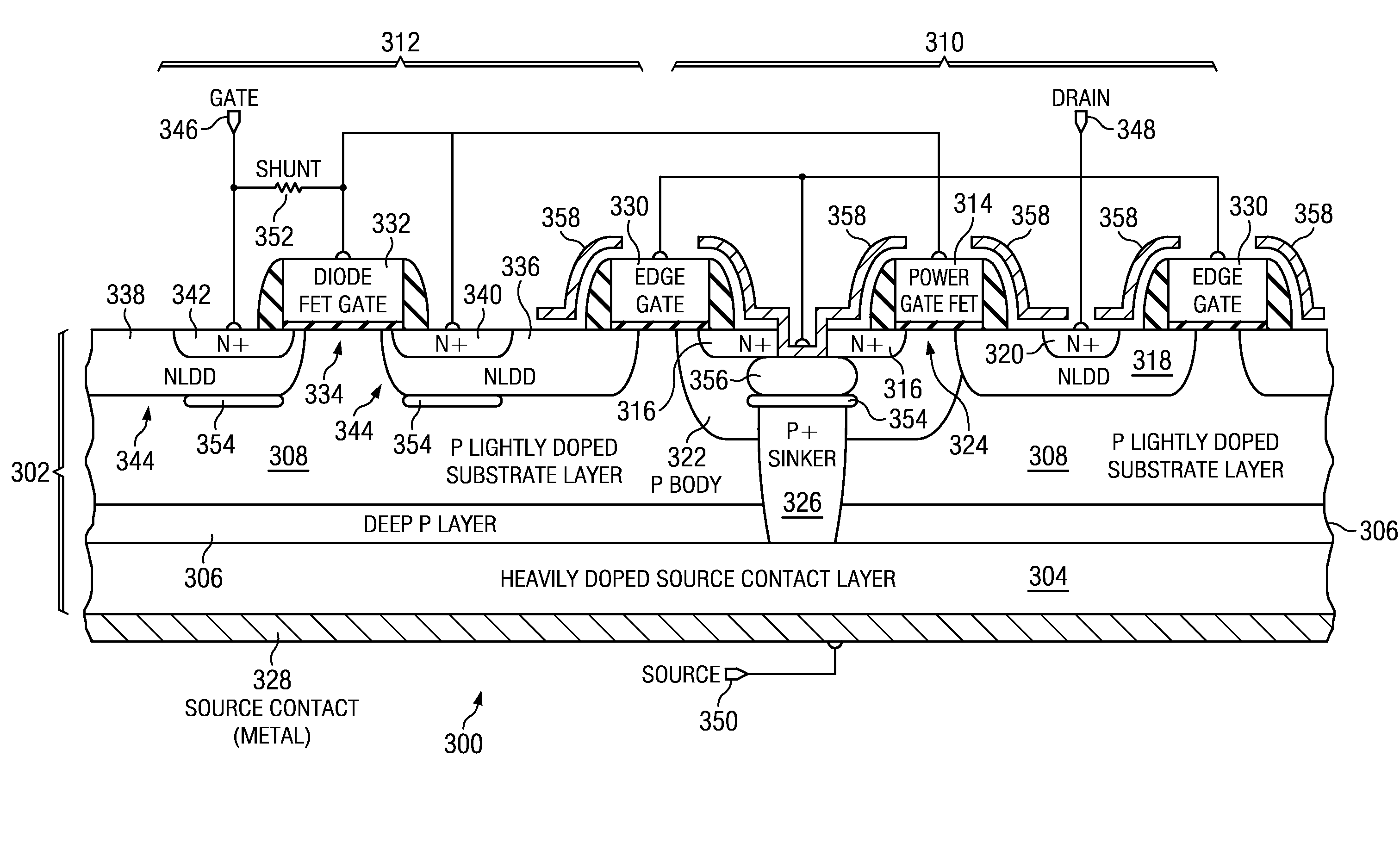
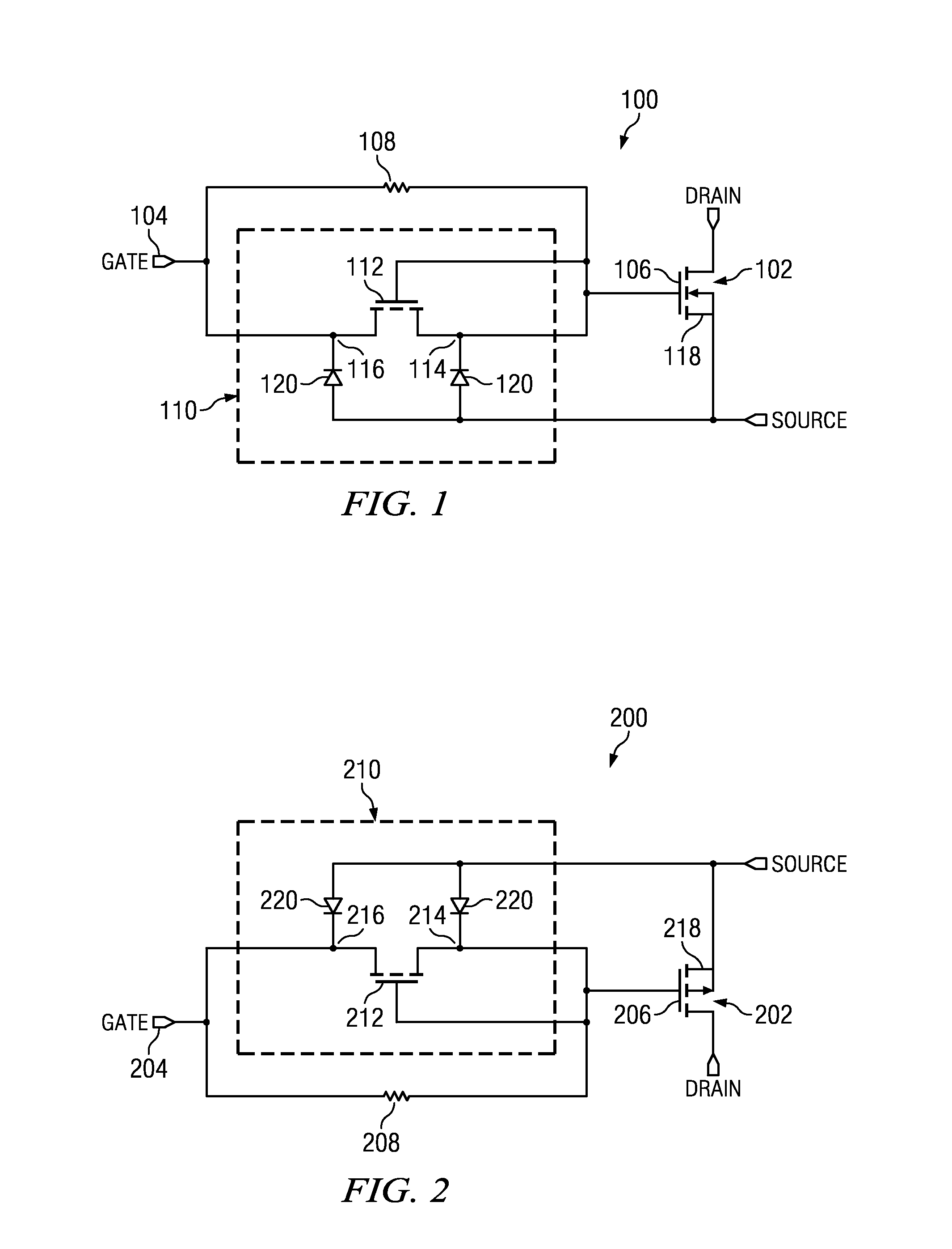
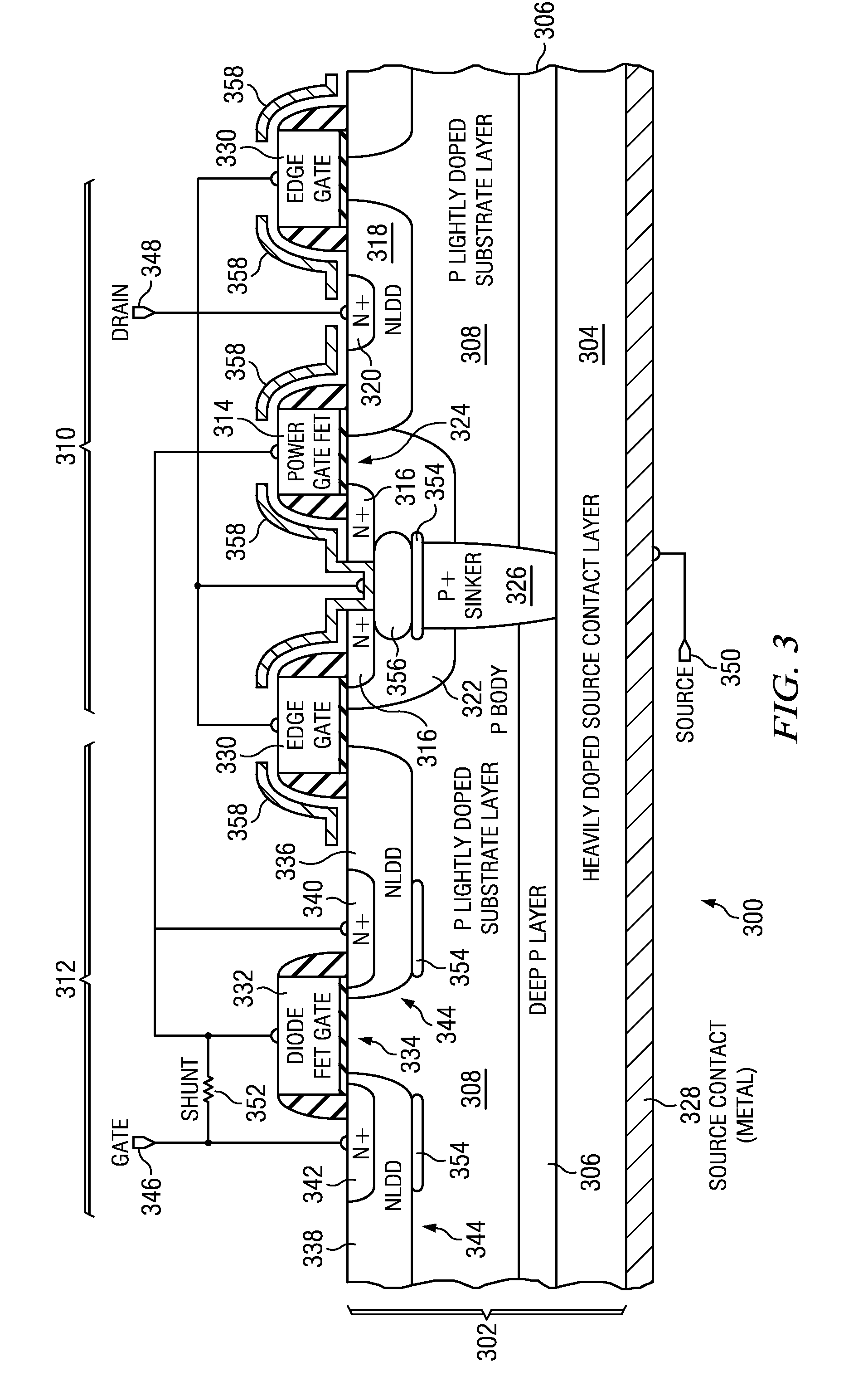
A power MOSFET is formed in a semiconductor device with a parallel combination of a shunt resistor and a diode-connected MOSFET between a gate input node of the semiconductor device and a gate of the power MOSFET. A gate of the diode-connected MOSFET is connected to the gate of the power MOSFET. Source and drain nodes of the diode-connected MOSFET are connected to a source node of the power MOSFET through diodes. The drain node of the diode-connected MOSFET is connected to the gate input node of the semiconductor device. The source node of the diode-connected MOSFET is connected to the gate of the power MOSFET. The power MOSFET and the diode-connected MOSFET are integrated into the substrate of the semiconductor device so that the diode-connected MOSFET source and drain nodes are electrically isolated from the power MOSFET source node through a pn junction.

Description

CROSS-REFERENCE TO RELATED APPLICATIONS[0001]This application claims the benefit of priority under U.S.C. §119(e) of U.S. Provisional Application 61 / 504,619 (Texas Instruments docket number TI-70952PS, filed Jul. 5, 2011).[0002]The following co-pending patent application is hereby incorporated by reference: U.S. patent application Ser. No. 12 / ______ (Texas Instruments docket number TI-70027, filed simultaneously with this application). With its mention in this section, this patent application is not admitted to be prior art with respect to the present inventionFIELD OF THE INVENTION[0003]This invention relates to the field of semiconductor devices. More particularly, this invention relates to power transistors.BACKGROUND OF THE INVENTION[0004]Power transistors in switching circuits may experience ringing when the power transistor is turned on and off. Snubbing components which desirably limit the ringing may undesirably reduce efficiency of buck converters containing the power trans...

Claims


Application Information

Patent Timeline
Patent Type & Authority Applications(United States)
IPC IPC(8): H01L27/06H01L21/336
CPCH01L27/0629H01L27/0727H01L29/402H01L29/4175H01L29/1083H01L29/456H01L29/66659H01L29/7835H01L29/861H01L29/41766
Inventor WANG, JUNXU, SHUMINGKOREC, JACEK
Owner TEXAS INSTR INC
Why Eureka
Try Eureka