Non-contact power feeding apparatus

a technology of power feeding apparatus and non-contact, which is applied in the direction of parallel operation of dc sources, transportation and packaging, rail devices, etc., can solve the problems of wasting power, difficulty in maintaining the stopping power supply device at ease, and the carriage may immediately run out of power, so as to reduce the risk of power feeding stop and save energy

Active Publication Date: 2013-01-10
DAIFUKU CO LTD
View PDF2 Cites 24 Cited by
  • Summary
  • Abstract
  • Description
  • Claims
  • Application Information

AI Technical Summary

Benefits of technology

[0005]Thus, the present invention has an object to provide a non-contact power feeding apparatus that solves these problems, can reduce the risk of stop of power feeding to a feeder, can save energy by supplying optimum power depending on varying power consumption, and can handle a stopping power supply device with safety.
[0007]Such a configuration provides technical advantages as described below:(1) Each power supply device is connected in series to the feeder via the transmission and receiving coupler, the plurality of power supply devices can supply power to the feeder. Thus, even if a power supply device with an abnormality is separated from the feeder, the other power supply device can continuously supply a current, thereby increasing reliability of the apparatus.(2) The power supply device can be separated (brought into a sleep state) depending on varying power consumption, thereby saving power while supplying optimum power, maintaining a constant current at that time, and preventing an influence on the feeder.(3) The transmission coupler of the transmission and receiving coupler is mechanically separated from the receiving coupler, and thus the power supply device can be electrically and mechanically separated from the feeder, thereby allowing safe maintenance of the power supply device.(4) The circuit on the side of the power line is set to the capacitive reactance, and thus when an output voltage of a pressure reducing circuit is controlled to perform feedback control to provide a constant current of the feeder, an increasing output voltage is smaller than an output voltage set by the capacitive reactance, thereby facilitating voltage control.

Problems solved by technology

(1) When the number of carriages exceeds an allowable number, a new power supply device is turned on, and power consumption of carriages changes in real time depending on changes in load (rotation number of a drive motor or the like) on the carriages. Thus, only with control of the number of carriages, power supply devices more than necessary may be turned on in the feeder, which may cause waste of power.
(2) On a side of the carriage, power is consumed irrespective of a state of the power supply device. Thus, when a problem occurs in the power supply device, the carriage may immediately run out of power.
(3) During supply of power from the other power supply device to the feeder, the short-circuit unit causes a short-circuit between a stopping power supply device and the feeder, and thereby the power supply device and the feeder are electrically separated, but connection between the stopping power supply device and the feeder is mechanically maintained. Thus, it is difficult to maintain the stopping power supply device at ease.

Method used


Image

  • Non-contact power feeding apparatus
  • Non-contact power feeding apparatus
  • Non-contact power feeding apparatus

Examples


embodiment 1

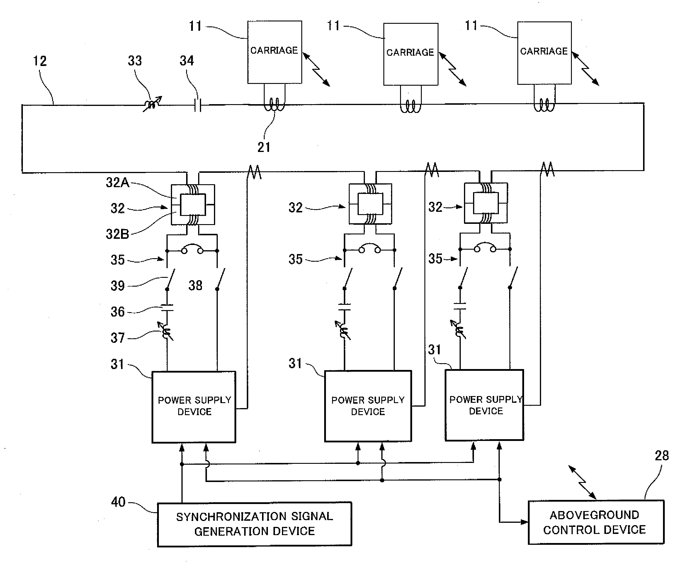
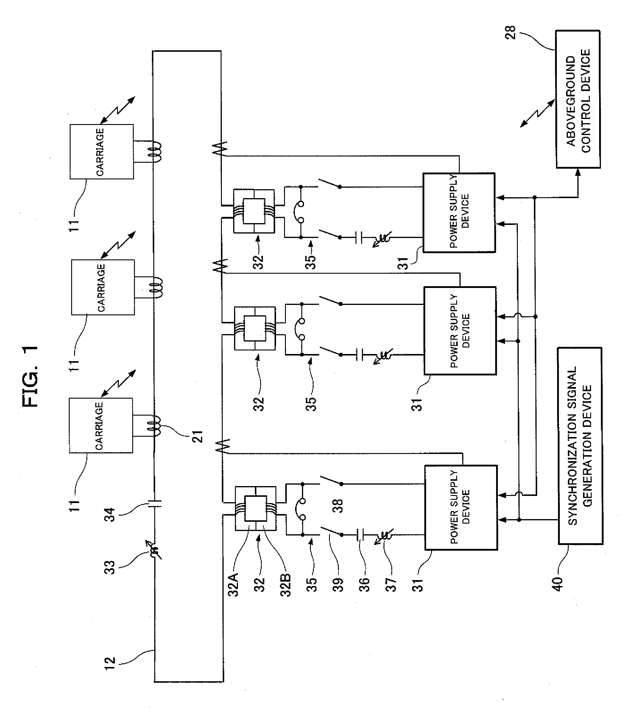
[0016]FIG. 1 is a configuration diagram of a non-contact power feeding apparatus in Embodiment 1. The non-contact power feeding apparatus supplies power to a plurality of carriages (an example of an object to which power is to be supplied) 11 in a non-contact manner, and a feeder 12 that supplies a constant current of a predetermined frequency f (for example, 10 kHz) is laid along a path of the carriages 11.

“Carriage”

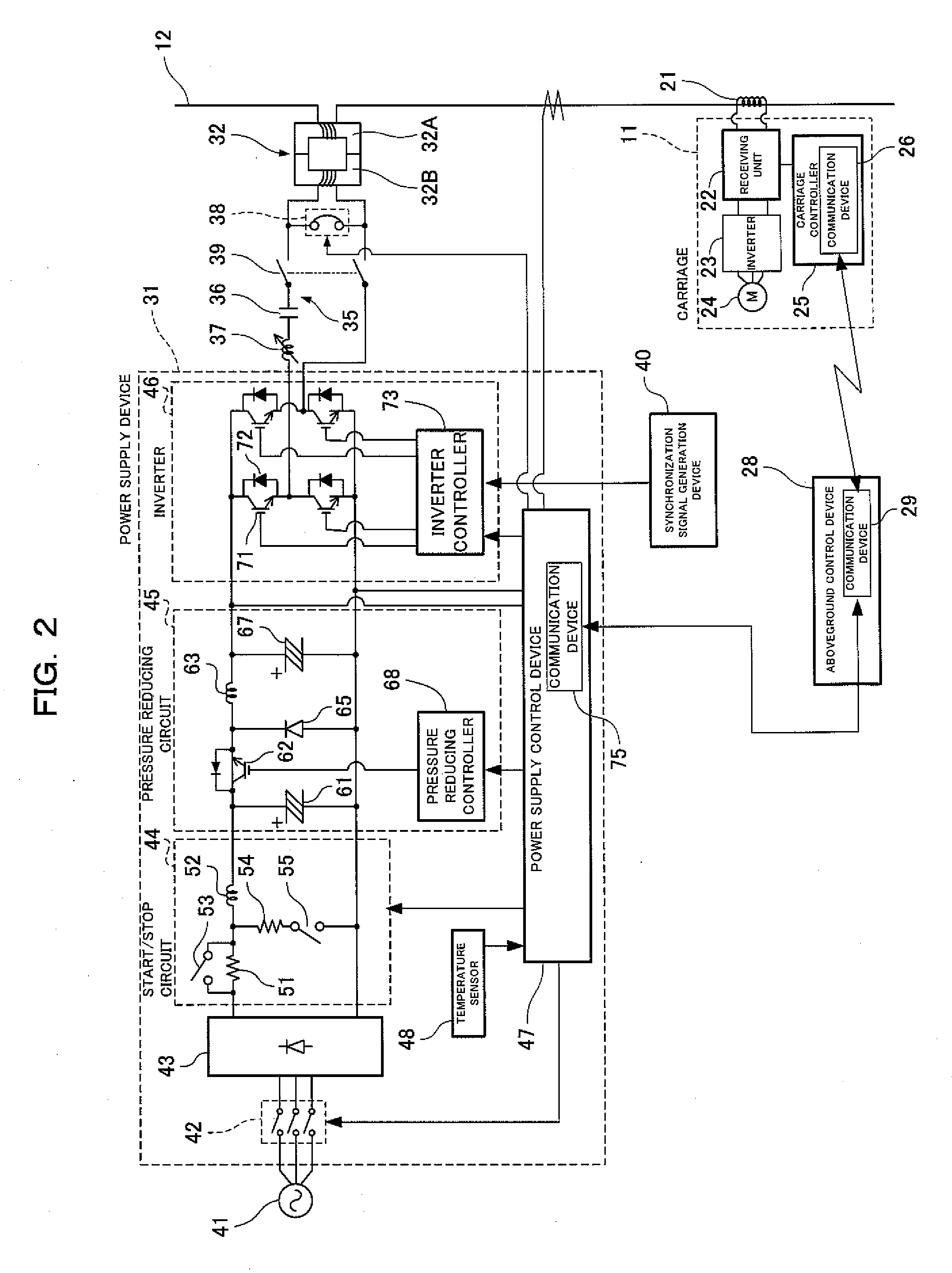
[0017]As shown in FIG. 2, the carriage 11 includes a receiving coil 21 in which an electromotive force is induced by the feeder 12. A receiving unit 22 is connected to the receiving coil 21, a drive motor (an example of a load with varying power consumption) 24 for causing the carriage 11 to travel is connected to the receiving unit 22 via an inverter 23, and power is supplied to the drive motor 24 by the electromotive force induced in the receiving coil 21. The carriage 11 also includes a controller (carriage controller) 25 for controlling traveling of the carriage 11,...

embodiment 2

[0068]As shown in FIG. 6, in a non-contact power feeding apparatus according to Embodiment 2 of the present invention, the short-circuit switch 38 and the manual switch 39 in Embodiment 1 are not required, and further, a circuit including a transmission coupler 32B, a capacitor 36, and a reactor 37 connected in series is a series resonant circuit (zero impedance) at a predetermined frequency f.

[0069]When a power supply device 31 is separated from a feeder 12, instead of a short-circuit switch 38 being short-circuited, an inverter controller 73 controls so that among switching elements 71 of an inverter 46, two upper switching elements 71 connected to a positive side of a DC current are not brought into conduction, but two lower switching elements 71 connected to a negative side of the DC current are brought into conduction of 180° according to a synchronization signal. When the switching element 71 is thus driven, no current flows from a pressure reducing circuit 45 as shown in FIG....


PUM


Abstract

Three power supply devices 31 are connected in series via a transmission and receiving coupler 32 to the feeder 12, a short-circuit switch 38 that short-circuits both ends of each transmission coupler 32B is provided, a circuit including three receiving couplers 32A and the feeder 12 is set to a series resonant circuit at a predetermined frequency f, impedance of a circuit including each transmission coupler 32B, and a line connecting the power supply device 31 and the transmission coupler 32B is set to capacitive reactance at the predetermined frequency f, and an voltage to be output to the circuit including the line is controlled while a current flowing through the feeder 12 is being fed back to output a constant current of the predetermined frequency f to the feeder.

Description

FIELD OF THE INVENTION[0001]The present invention relates to a non-contact power feeding apparatus that supplies power from a power supply device to an object to which power is to be supplied in a non-contact manner.BACKGROUND OF THE INVENTION[0002]As disclosed in, for example, Japanese Patent No. 4100168, a known non-contact power feeding apparatus is configured so that a plurality of power supply devices that supply currents with synchronized current phases are connected in series to a feeder, and during power feeding, a power supply device is turned on in the feeder depending on the number of carriages to which power is to be supplied so that power can be supplied depending on the number of carriages.[0003]The non-contact power feeding apparatus is configured so that a short-circuit unit causes a short-circuit between a current device and the feeder without stopping the entire power feeding apparatus, and thus only any one of the power supply devices can be stopped (separated) du...

Claims


Application Information

Patent Timeline
Patent Type & Authority Applications(United States)
IPC IPC(8): H02J17/00B60L5/00B60M7/00
CPCH02J5/005B60M7/00H02J2310/40H02J50/50H02J50/80H02J50/12H02J50/005H04B5/0037H04B5/0075
Inventor NUNOYA, MAKOTOMUROTA, AKIRA
Owner DAIFUKU CO LTD
Why Eureka
Try Eureka