
Projection image generation apparatus, program and method

Active Publication Date: 2013-01-10
FUJIFILM CORP
View PDF6 Cites 15 Cited by
  • Summary
  • Abstract
  • Description
  • Claims
  • Application Information

AI Technical Summary

Benefits of technology

The patent describes a way to generate a two-dimensional projection image of a tubular structure, such as a blood vessel, from 3D data. This allows for easier identification of abnormal positions, like narrowing or blockages. The method also prevents branching paths from overlapping each other. The resulting image can be easily understood by a doctor or other observer. The technical effect of this patent is to provide a more precise and accurate way to visualize the shape and details of tubular structures.

Problems solved by technology

However, when tubular structures of branching plural paths are displayed at the same time, there is an unobservable region in some cases, because the paths overlap each other.
However, in the method of Non-Patent Document 1, an unobservable region is generated in some cases, because paths overlap each other.
Therefore, a corresponding relationship with an actual anatomical position becomes unclear, and even if a stenosis region in a blood vessel is recognized in a CPR image, there is a problem that it is difficult to recognize at which position the stenosis has occurred in actual coronary arteries.

Method used


Image

  • Projection image generation apparatus, program and method
  • Projection image generation apparatus, program and method
  • Projection image generation apparatus, program and method

Examples


Embodiment Construction

[0057]Hereinafter, embodiments of a projection image generation apparatus and a projection image generation program and method according to the present invention will be described in detail with reference to drawings.

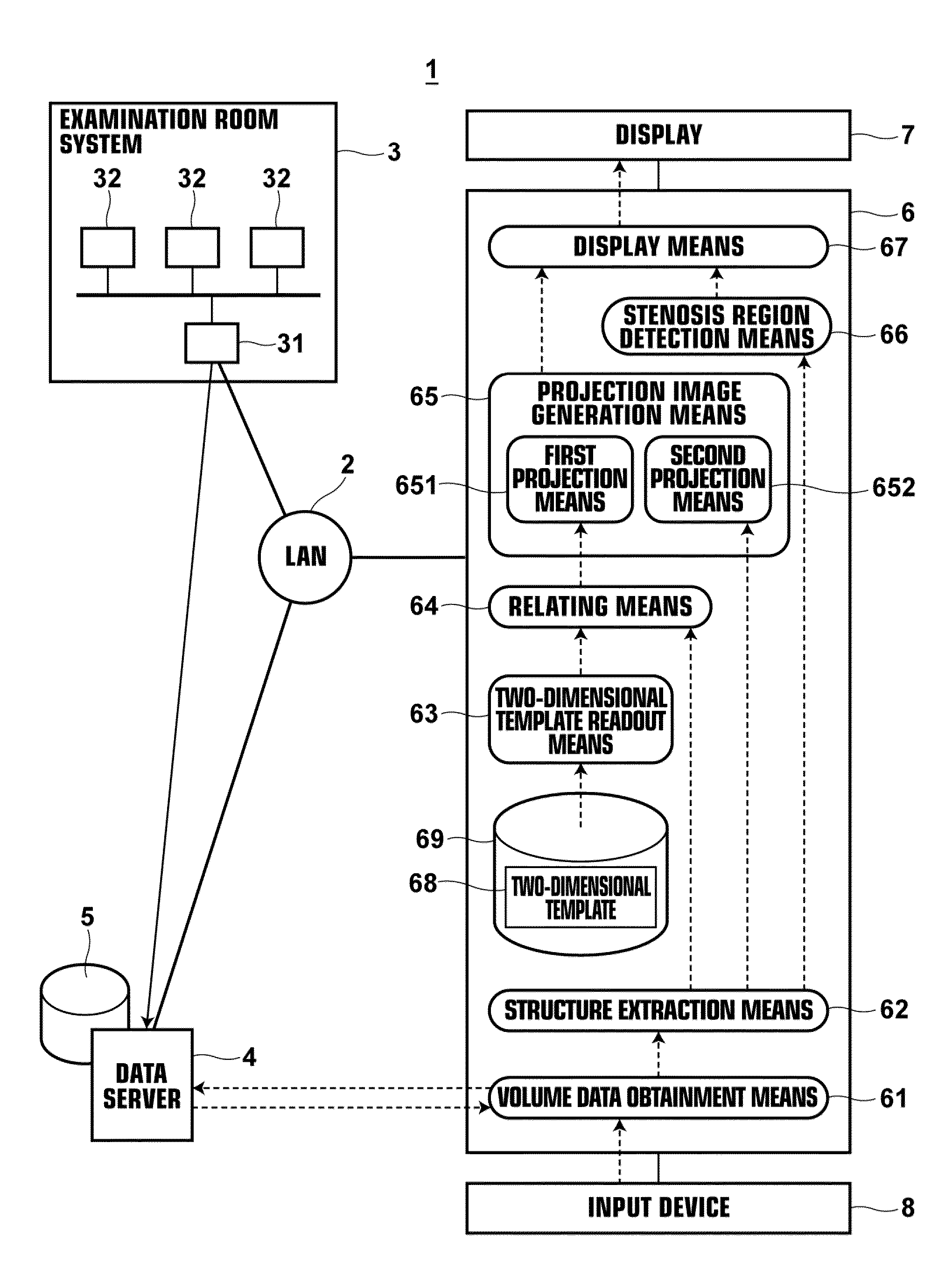
[0058]FIG. 1 is a schematic diagram illustrating the configuration of a hospital system including a projection image generation apparatus according to an embodiment of the present invention. The hospital system 1 includes an examination room system 3, a data server 4 and a workstation (WS) 6 for diagnosis, which are connected to each other through a local area network (LAN) 2.

[0059]The examination room system 3 includes various modalities 32 for imaging a subject to be examined and an examination room workstation (WS) 31. The examination room workstation (WS) 31 is used to check and adjust an image output from each modality. As the modalities 32, for example, an X-ray radiography apparatus, a CT (Computed Tomography) apparatus, an MRI (Magnetic Resonance Imaging) appara...


PUM


Abstract

A structure extraction element obtains three-dimensional structure extraction data by extracting a tubular structure from volume data obtained by imaging a predetermined subject. A relating element relates positions on paths of a two-dimensional template representing a schematic diagram of a three-dimensionally branching tubular structure obtained by imaging a predetermined subject and positions on paths of the three-dimensional structure extraction data to each other. A projection image generation element generates a two-dimensional projection image by projecting voxel values of the tubular structure that is present on the paths of the three-dimensional structure extraction data onto corresponding positions on the paths of the two-dimensional template.

Description

BACKGROUND OF THE INVENTION[0001]1. Field of the Invention[0002]The present invention relates to a projection image generation apparatus, program and method for generating a projection image by projecting a three-dimensional tubular anatomical structure in three-dimensional data onto a two-dimensional plane.[0003]2. Description of the Related Art[0004]In recent years, high-quality three-dimensional images (volume data) became used in image-based diagnosis as medical equipment (for example, a multi-detector CT, or the like) advanced. Volume data are composed of many two-dimensional images, and the information amount of the volume data is large. Therefore, in some cases, a doctor needs a time to find a desired observation region to diagnose a patient. Therefore, an improvement of a characteristic of recognizing a whole organ and a lesion was attempted by extracting and displaying an organ of interest by MIP, VR, CPR, or the like, thereby improving the efficiency of diagnosis.[0005]Esp...

Claims


Application Information

Patent Timeline
IPC IPC(8): G06T17/00
CPCA61B6/032A61B6/503G09B23/30G06T7/0083G06T15/08G06T2215/06G06T2207/20016G06T2207/20072G06T2207/30048G06T2207/30101G06T2207/30172G06T2207/10072G06T2210/41G06T7/12
Inventor KITAMURA, YOSHIRO
Owner FUJIFILM CORP
Learn More