Display device

a technology of display device and liquid crystal, applied in the field of display device, can solve the problem of low light-use efficiency of liquid crystal display device using color filter, and achieve the effect of minimizing the influence of temperatur

Active Publication Date: 2013-01-10
SHARP KK
View PDF3 Cites 19 Cited by
  • Summary
  • Abstract
  • Description
  • Claims
  • Application Information

AI Technical Summary

Benefits of technology

[0044]According to the twelfth aspect, the display device has the thermometer provided on the display panel, and the correction signals stored in the look-up table are correlated to the input signals for each piece of temperature information. Thus, the color correction circuit can read the correction signals from the look-up table in accordance with the temperature information provided by the thermometer. In this case, the display device displays an image in accordance with a correction signal corresponding to the temperature of the display panel, and therefore the influence of the temperature can be minimized even if the display speed of the display device varies in accordance with the temperature.

Problems solved by technology

However, about ⅔ of backlight irradiated on a liquid crystal panel is absorbed by the color filters, and therefore liquid crystal display devices using color filters have a problem of low light-use efficiency.

Method used


Image

  • Display device
  • Display device
  • Display device

Examples


first embodiment

1. First Embodiment

[0066]

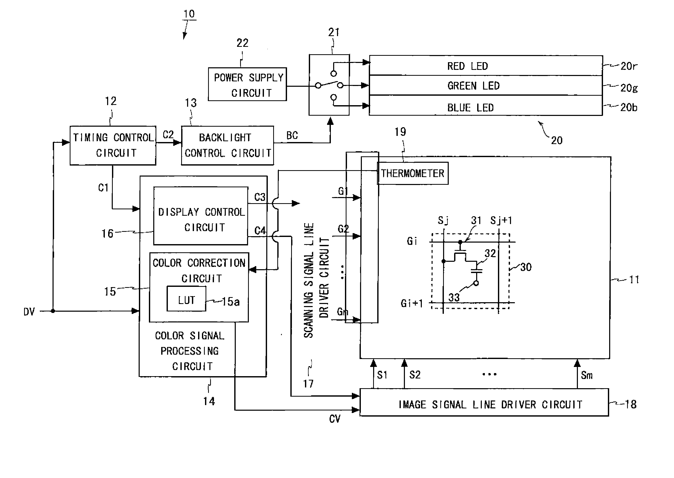
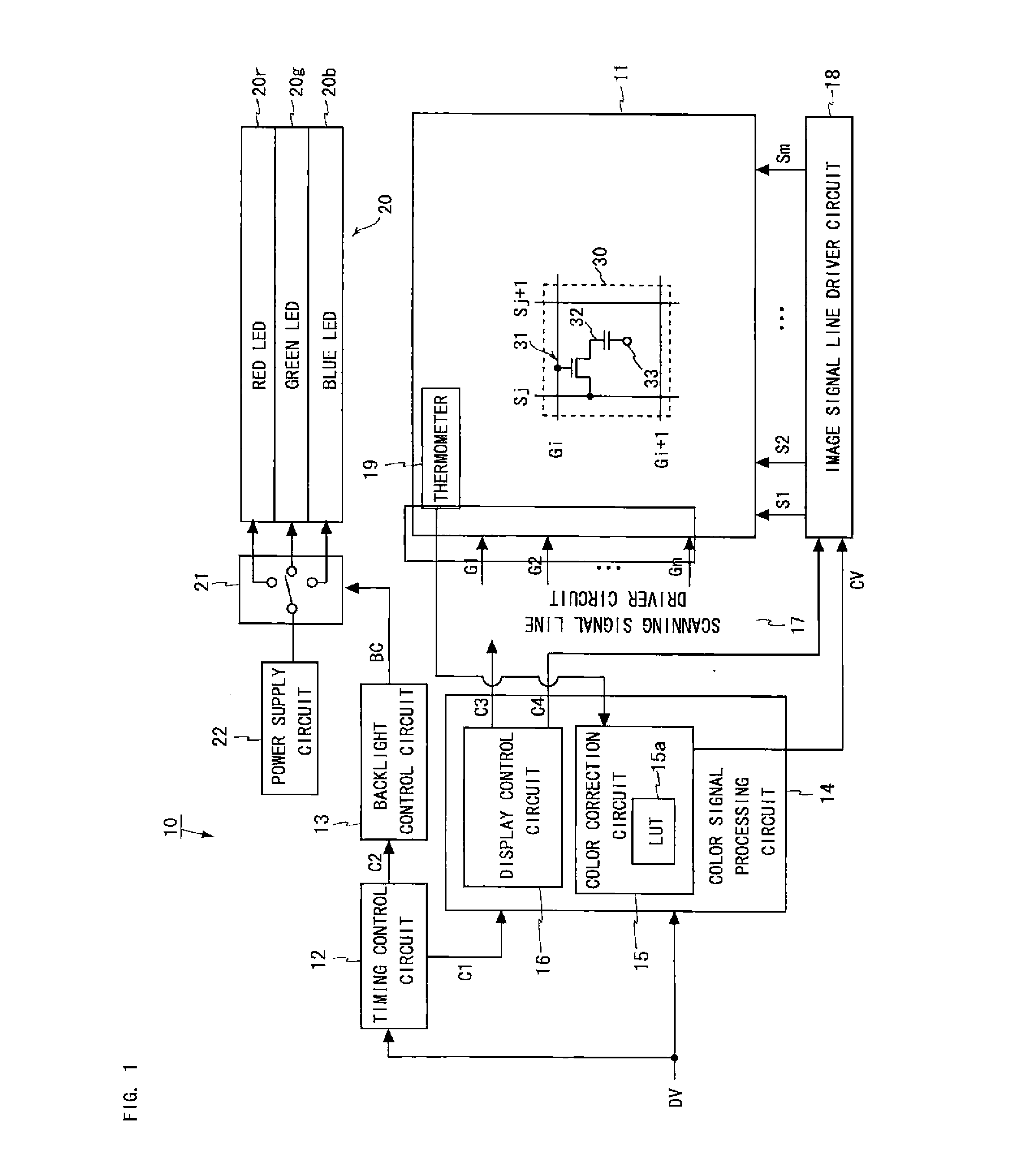
[0067]FIG. 1 is a block diagram illustrating the configuration of a field-sequential liquid crystal display device 10 according to a first embodiment of the present invention. The liquid crystal display device 10 shown in FIG. 1 provides color display using a field-sequential color system in which one frame period is divided into three subframe periods. The liquid crystal display device 10 includes a liquid crystal panel 11, a scanning signal line driver circuit 17, an image signal line driver circuit 18, a thermometer 19, a color signal processing circuit 14, a timing control circuit 12, a backlight control circuit 13, a backlight unit 20, a switch 21, and a power supply circuit 22.

[0068]In the following, for example, one frame period is 1 / 60 of a second, and each subframe period is 1 / 180 of a second. Moreover, each of the red, green, and blue components of an input signal externally provided to the liquid crystal display device 10 is 8-bit data. In this ca...

second embodiment

2. Second Embodiment

[0125]A liquid crystal display device according to a second embodiment will be described. The configuration of the liquid crystal display device according to the present embodiment is the same as the configuration of the liquid crystal display device 10 shown in FIG. 1, and therefore any illustration and description thereof will be omitted. In the present embodiment, pixel display points on each side of hexagon F shown in FIG. 4 are obtained by computation, along with the pixel display points obtained by computation in the first embodiment. Accordingly, a description will be given taking as an example the case where pixel display points on side RY, one of the sides of hexagon F, are obtained.

[0126]The input signal DV (255,0,0) expected to represent the primary color red corresponding to primary-color chromaticity point r and the input signal DV (255,255,0) expected to represent the primary color yellow corresponding to primary-color chromaticity point y are the s...

third embodiment

3. Third Embodiment

[0145]A liquid crystal display device according to a third embodiment will be described. The configuration of the liquid crystal display device according to the present embodiment is the same as the configuration of the liquid crystal display device 10 shown in FIG. 1, and therefore any illustration and description thereof will be omitted.

[0146]FIG. 15 is a chromaticity diagram showing the range of color reproduction by the liquid crystal display device of the present embodiment in a u′v′ coordinate system. As shown in FIG. 15, smooth curves connect primary-color chromaticity points r, y, g, c, b, and m to white point W. These curves respectively pass pixel display points R, Y, G, C, B, and M corresponding to their respective primary-color chromaticity points r, y, g, c, b, and m. Next, input signals DV are converted to correction signals CV specifying pixel display points that correspond to 255 equal parts for each curve. As a result, pixel display points R, Y, G...


PUM


Abstract

The present invention aims to provide a display device capable of displaying an image in a color maintaining a hue and a tone expected from an input signal.
In a field-sequential liquid crystal display device, when a red image is displayed, red light is transmitted in the first subframe period, and further, green light and blue light are transmitted in the second and third subframe periods, respectively. Therefore, the blue component of an input signal is adjusted such that the transmittance of the liquid crystal panel is at a predetermined value even in the third subframe period. As a result, the hue of an image displayed on the liquid crystal panel is the same as or almost the same as the hue of red expected from the input signal. Moreover, the color of red displayed on the liquid crystal panel maintains the tone value of the color expected from the input signal.

Description

REFERENCE TO RELATED APPLICATIONS[0001]This application is a national stage application under 35 USC 371 of International Application No. PCT / JP2011 / 053791, filed Feb. 22, 2011, which claims the priority of Japanese Patent Application No. 2010-095965, filed Apr. 19, 2010, the entire contents of which are incorporated herein by reference.FIELD OF THE INVENTION[0002]The present invention relates to display devices, more specifically to a display device, such as a liquid crystal display device, which provides color display using a field-sequential system.BACKGROUND OF THE INVENTION[0003]Most of the liquid crystal display devices that provide color display include sets of color filters for transmitting red (R), green (G), and blue (B) light therethrough, such that one set is provided for every three subpixels into which one pixel is divided. However, about ⅔ of backlight irradiated on a liquid crystal panel is absorbed by the color filters, and therefore liquid crystal display devices u...

Claims


Application Information

Patent Timeline
Patent Type & Authority Applications(United States)
IPC IPC(8): G09G5/10G09G3/20
CPCG09G3/3648G09G2320/0242G09G2310/0235
Inventor KOBAYASHI, MASAMITSUISHIHARA, TOMOYUKI
Owner SHARP KK
Why Eureka
Try Eureka