Manhole cover optimized for manufacturing

a manhole cover and manufacturing technology, applied in the field of manhole covers, can solve the problems of complex production of manhole covers, high cost of components or materials, and high cost of manhole covers, and achieve the effects of reducing the load applied, enhancing the cost of manhole covers, and reducing the load

Active Publication Date: 2013-01-10
THOMAS LORENZ INDTECHN
View PDF12 Cites 15 Cited by
  • Summary
  • Abstract
  • Description
  • Claims
  • Application Information

AI Technical Summary

Benefits of technology

[0024]The inexpensive production of the manhole cover may advantageously be enhanced by providing not just one, but two, lifting handles that are arranged diametrically opposed to each other. In this way, the cover may be lifted or lowered without tilting, which, in contrast to the use of only a single lifting handle, reduces the loads applied to the manhole cover because, for example, the use of two lifting handles reduces canted loading on the cover, caused by a diagonal orientation of the cover. Also, the use of two handles reduces the loading on the individual lifting handles and the locations where the lifting handles are anchored in the filling. Despite the greater use of materials, the arrangement of two lifting handles instead of one lifting handle surprisingly reduces the cost of production of the manhole cover, because the manhole cover may now be constructed to withstand these lesser loads.
[0025]Advantageously, the lifting handle may be formed from a wire, preferably a rust-free, stainless steel wire, the two ends of which are anchored in the filling, whereby a recess is provided in the filling through which the wire extends, so that the mid-section of the wire runs inside the recess and can be gripped from underneath with appropriate lifting tools. This recess ensures a countersunk arrangement of the lifting handles, so that they do not protrude above the surface of the manhole cover, and this reduces the loads applied to the lifting handles because of someone walking or driving over the manhole cover, etc.
[0026]The lifting handle may advantageously be immovably anchored in the filling, instead of being movable between an idle and an operational position. This simplifies the production of the manhole cover, and also makes it more economical. Since one can assume that, in most applications, the manhole cover will not have to be removed from the manhole on a daily or weekly basis, but rather, at most, at intervals of several months or even several years, a manhole cover construction that entails additional costs and that possibly facilitates the handling of the lifting handle does not make economic sense in most such cases. In view of the long intervals between instances when the lifting handle is used, it is also questionable whether, if need be, such a lifting handle can actually be moved easily or is possibly ...

Problems solved by technology

The production of this manhole cover, which overall comprises a three-layer construction, is therefore technically complicated.
The components or materials used are relatively expensive.
The production of the manhole cover is complicated, because a hollow body must be filled, whereby providing the openings in the hollow body necessary for the vertical mobility of the lifting handles complicates the filling process. or, if the openings are not formed in the filling process, after the filling has hardened, several through-bor...

Method used


Image

  • Manhole cover optimized for manufacturing
  • Manhole cover optimized for manufacturing
  • Manhole cover optimized for manufacturing

Examples


Embodiment Construction

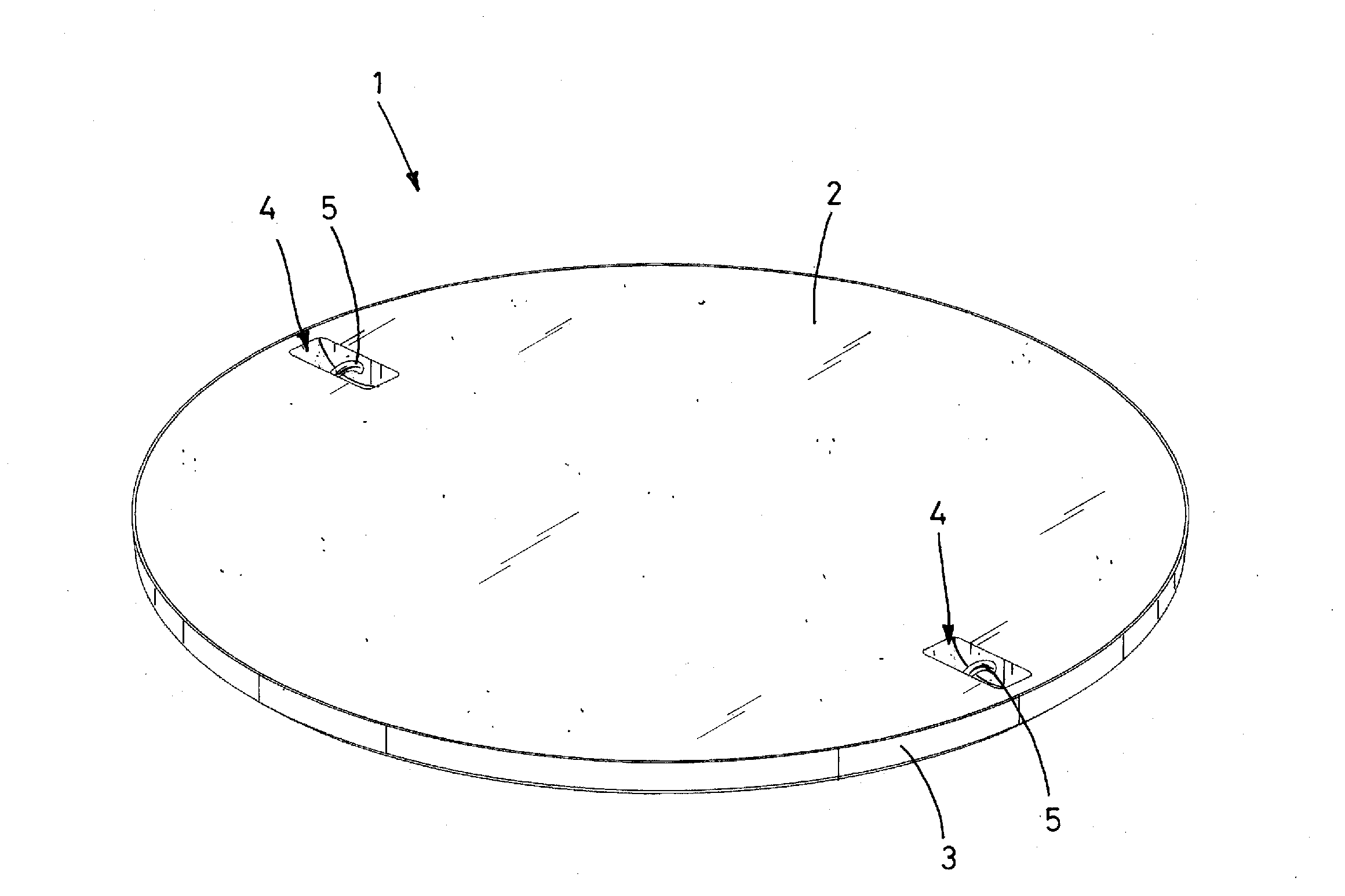
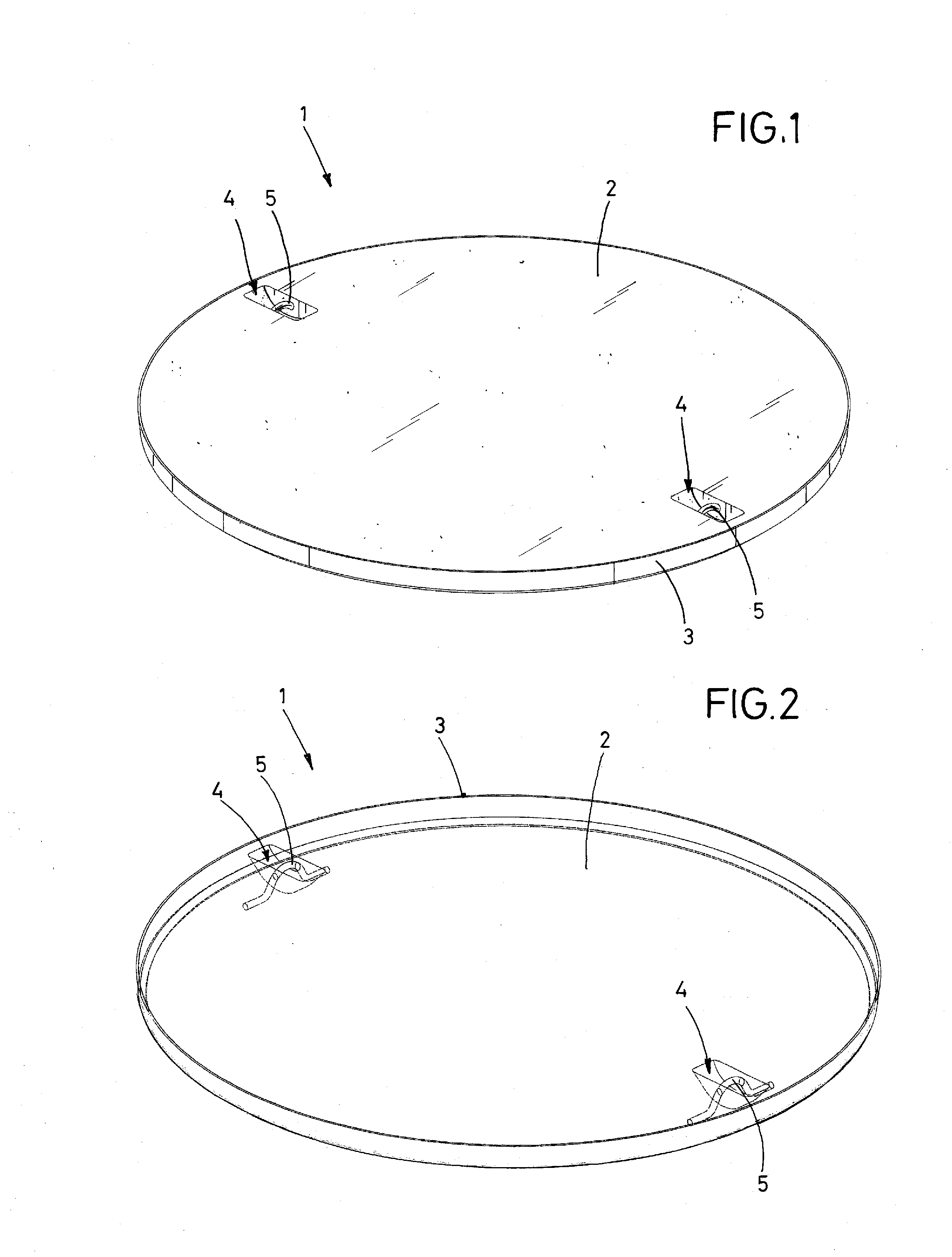
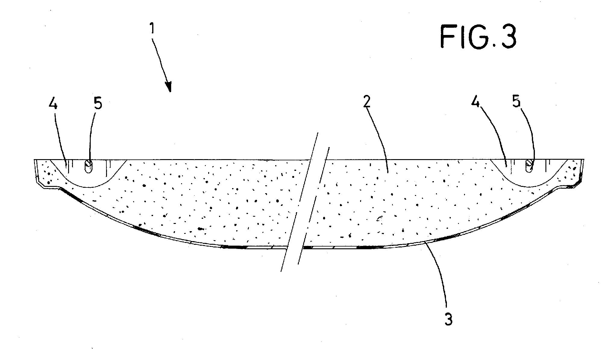
[0034]FIGS. 1-3 illustrate a manhole cover 1, which is essentially made of concrete. A plastic saucer-shaped shell 3 serves as a form for a concrete casting. A concrete mixture or filling 2 is poured into the shell 3 to form a base 3. The base 3 thus has the form of a filled saucer, whereby the shell 3 remains as part of the base 3 and serves as an outer bottom surface and as a side wall of the manhole cover 1.

[0035]In the embodiment shown, two recesses 4 are formed in the filling 2, the recesses 4 positioned diametrically opposite each other. A lifting handle 5 is provided in each recess 4. The lifting handle is preferably a length of wire, the free ends of which are anchored in the filling 2.

[0036]As shown in FIG. 2, the lifting handle 5 has a middle portion that is curved, with two straight ends embedded in the filling 2. The curved portion extends upward in the recess, so as to provide a space between the middle portion and the bottom of the recess 4. This construction has the a...


PUM


Abstract

A manhole cover is made of a fiberglass reinforced saucer-like shell that is filled with concrete. The interior surface of the shell is rough and the shell has a maximum thickness of 5 mm. An adhesive agent may be provided between the base and the filling, to obtain a reliable bond between base and filling. The concrete for the filling may be pure mineral concrete. One or more lifting handles are embedded in the filling. To this end, a recess for each handle is formed in the filling. The ends of the handle are embedded in the concrete and the lifting portion of the handle is curved upward and is held in the recess such that there is a space between the curved portion and the bottom of the recess, so that the handle may be easily grasped.

Description

BACKGROUND INFORMATION[0001]1. Field of the Invention[0002]The invention relates to a manhole cover that is particularly simple and inexpensive to manufacture.[0003]2. Discussion of the Prior Art[0004]GB 2 145 444 A, the closest prior art, discloses a manhole cover that comprises only the two components of a base and a filling. The preferred material for the base of the manhole cover is the same material that is used for a manhole that is to be covered by the manhole cover, whereby, high-density polyethylene is named as an example. The manhole serves as access to the sewage system for inspection purposes. The disclosure does not mention how the manhole cover is arranged and what loads it can withstand.[0005]An unconventional manhole cover is disclosed in DE 298 01 640 U1. This manhole cover has a metal outer shell on its bottom side, into which the actual base, which has a certain layer thickness, is then cast, whereby the filling is then cast into the base. The production of this m...

Claims


Application Information

Patent Timeline
IPC IPC(8): E02D29/14
CPCE02D29/14Y10T137/7021
Inventor LORENZ, THOMAS
Owner THOMAS LORENZ INDTECHN
Why Eureka
Try Eureka