Liquefier with pressure-controlled liquefaction chamber

a liquefier and liquefaction chamber technology, applied in the field of liquefiers, can solve the problems of reducing the efficiency of liquefiers and reliquefiers, increasing the cost associated with dewar, and loss of cryogen, so as to improve the efficiency of liquefying gas, reduce the pressure, and increase the cooling power of cryocoolers.

Active Publication Date: 2013-01-17
QUANTUM DESIGN
View PDF6 Cites 22 Cited by
  • Summary
  • Abstract
  • Description
  • Claims
  • Application Information

AI Technical Summary

Benefits of technology

[0015]The improved gas liquefaction system disclosed herein provides an apparatus and method for liquefying gases at pressures above 1.0 bar such that the system is adapted to: (i) take advantage of the higher cooling power of the cryocooler at higher temperatures to liquefy the gas more efficiently; (ii) eliminate the problem of storing a cryogenic liquid at high pressures; (iii) eliminate the need to lower the pressure in the storage portion of the Dewar to ambient pressure before removing the liquid cryogen; (iv) eliminate the loss of cryogen associated with lowering the pressure in the storage portion of the Dewar to ambient pressure; and (v) allow the liquefaction process to proceed simultaneously while the user is removing liquid cryogen from the storage portion of the Dewar. In particular the system is adapted to liquefy helium gas at an elevated pressure (and temperature) near the critical point of liquid helium for achieving improved liquefaction efficiency of helium. For helium, the pressure at the critical point is about 2.2 bar.
[0017]In various embodiments, the liquefier is adapted to actively monitor and dynamically regulate pressure within the liquefaction chamber for providing efficient liquefaction of gas. For example, a pressure sensor and / or a thermometer may be coupled to a CPU for measuring at least one of pressure and temperature within the liquefaction region of the liquefier. In this regard, the system is adapted to monitor liquefaction conditions such as pressure and temperature within the liquefaction chamber, and can further regulate the liquefaction of gas therein by increasing pressure within the liquefaction chamber (inserting high-pressure gas), decreasing pressure (exhausting gas), switching on / off the cryocooler, or other functions. Thus, the liquefier can be dynamically controlled for optimizing liquefaction conditions and thereby controlling the efficiency of the liquefier.

Problems solved by technology

These liquefiers and reliquefiers, however, are limited with respect to liquefaction efficiency, or the amount of liquefied cryogen that can be generated using a given cryocooler over a period of time.
This creates several serious problems: (i) Holding large cryogenic containers at high pressures is dangerous and further requires that the Dewar meet rigid safety requirements, thereby increasing the cost associated with the Dewar; (ii) before extracting the liquid cryogen, the Dewar pressure must be lowered to about 1.0 bar which results in the loss of a substantial amount of cryogen; and (iii) when lowering the pressure in the Dewar and removing the liquid cryogen from the Dewar, the system cannot simultaneously continue the liquefaction process at the optimum liquefaction pressure.
To date, no instrument for liquefaction of gas has yet been developed that allows a gas to be liquefied at elevated pressures, stored at or near ambient pressures and further allows the user to extract the liquid cryogen from the Dewar while simultaneously continuing to liquefy gas at the optimal pressure.

Method used


Image

  • Liquefier with pressure-controlled liquefaction chamber
  • Liquefier with pressure-controlled liquefaction chamber
  • Liquefier with pressure-controlled liquefaction chamber

Examples


Embodiment Construction

[0033]In the following description, for purposes of explanation and not limitation, details and descriptions are set forth in order to provide a thorough understanding of the present invention. However, it will be apparent to those skilled in the art that the present invention may be practiced in other embodiments that depart from these details and descriptions without departing from the spirit and scope of the invention. Certain embodiments will be described below with reference to the drawings wherein illustrative features are denoted by reference numerals.

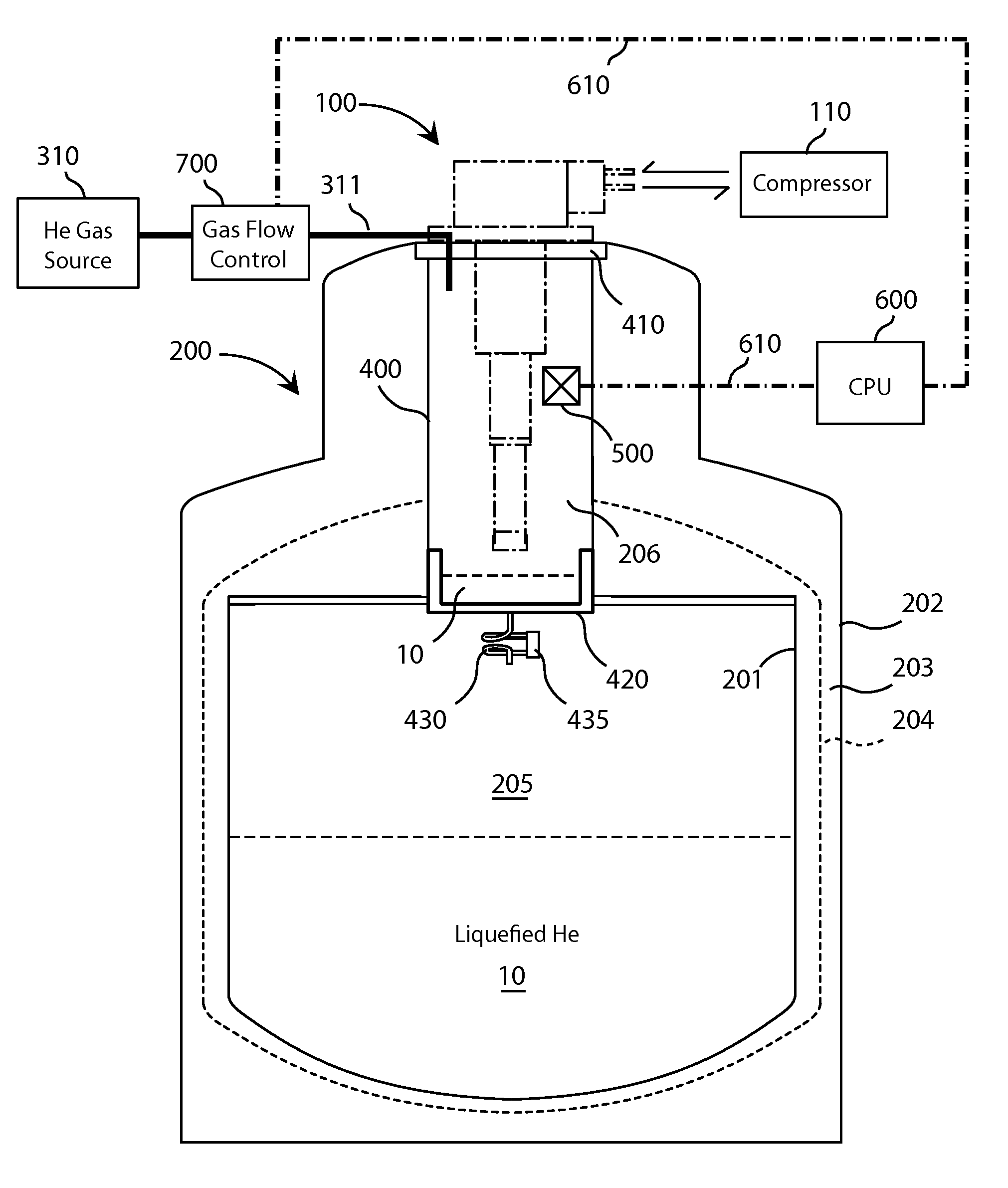
[0034]In a general embodiment, a liquefier comprises a storage portion and a liquefaction chamber that is sealed from the storage portion such that liquefaction of gas is performed within the liquefaction chamber under isolated conditions from the storage portion; i.e. elevated pressure. In this regard, the liquefaction region of the chamber is generally pressurized above atmospheric pressure during the process of gas liquefacti...


PUM


Abstract

A liquefier includes a Dewar having a storage portion and a neck portion extending therefrom. A hermetically isolated liquefaction chamber is disposed within the neck of the Dewar. One or more control components including a temperature and pressure sensor are coupled to a CPU and disposed within the liquefaction chamber for dynamic control of liquefaction conditions. A gas flow control is coupled to the CPU for regulating an input gas flow into the liquefaction chamber. A volume surrounding the liquefaction chamber may be adapted to provide a counter-flow heat exchange. These and other features provide improved liquefaction efficiency among other benefits.

Description

CROSS-REFERENCE TO RELATED APPLICATIONS[0001]This application claims priority to U.S. Provisional Ser. No. 61 / 507,595, filed Jul. 14, 2011; which is hereby incorporated by reference.BACKGROUND OF THE INVENTION[0002]1. Field of the invention[0003]This invention relates to gas liquefaction systems, or “liquefiers”; and more particularly to a liquefier having an isolated liquefaction chamber adapted for dynamic pressure-control for achieving improved liquefaction efficiency.[0004]2. Related Art[0005]Gas liquefaction systems, also referred to as “liquefiers”, are well documented in the art and generally comprise a vacuum insulated container known as a Dewar, the Dewar being adapted to receive at least a portion of a cryocooler for liquefying gas, and further comprising a storage portion for storing an amount of liquefied gas therein.[0006]FIG. 1 illustrates a liquefier comprising a Dewar 200 and a cryocooler 100 extending within a neck portion 206 of the Dewar. Within these systems, suc...

Claims


Application Information

Patent Timeline
Patent Type & Authority Applications(United States)
IPC IPC(8): F25J1/00F25B9/00
CPCF25D19/00F25J1/0007F25J1/0225F25J1/0244F25J1/0276F25J2270/908F25J2230/24F25J2230/30F25J2270/912F25J1/0236F25J1/0294F25B2400/17F17C3/085F17C13/006F17C13/007F17C13/04F17C2205/0391
Inventor DIEDERICHS, JOSTSAGER, RONALD
Owner QUANTUM DESIGN
Why Eureka
Try Eureka