
Traffic declineator barrel

a technology of barrel delineator and barrel flange, which is applied in the direction of roads, roads, constructions, etc., can solve the problems of cracks and breaking of high stress regions, significant wear and tear of the flange piece of the handle and bottom rim, and the cracks and breaking of the flange at high stress regions, so as to enhance the rigidity of the adjoining region, improve the rigidity of the barrel, and the effect of durable single wall plastic construction

Active Publication Date: 2013-01-17
POLY FLEX INC
View PDF4 Cites 3 Cited by
  • Summary
  • Abstract
  • Description
  • Claims
  • Application Information

AI Technical Summary

Benefits of technology

The patent describes a molded barrel type delineator that is designed to have stronger and more rigid regions. The method used to construct the barrel involves manipulating the mold to create struts or pillars that reinforce the high stress regions. These modifications enhance the durability of the barrel and make it more resistant to damage. Overall, the patent provides a solution for creating a long-lasting and reliable delineator barrel.

Problems solved by technology

The portability of the barrel and exposure to the normal roadway environment subjects the handle and bottom rim flange pieces to significant wear and tear due to the repeated deployment and re-deployment of the barrels as a job progresses or with each new job.
A primary problem with a single walled barrel construction is that cracks and breaking can occur at high stress regions exposed to the most handling, wear and tear, particularly and for example the handle and bottom rim flange.
Damage to the flexible bottom rim flange occurs from the frequent flexing that occurs as road crewmen mount the barrel to a ballast base piece.
In cold weather the flexing can produce cracks and splits in the barrel sidewalls and base.
The setup time and related cost is also frequently extended due to the foregoing difficulties.
Detachment of the body of the barrel from the ballast base can also be frustrated if the rim flange is too flexible.
Fabrication costs increase however if the bonding occurs after molding whether the barrel warm or cold since it is necessary to separately handle and manipulate the barrel to compress and bond the selected adjoining wall surfaces.

Method used


Image

  • Traffic declineator barrel
  • Traffic declineator barrel
  • Traffic declineator barrel

Examples


Embodiment Construction

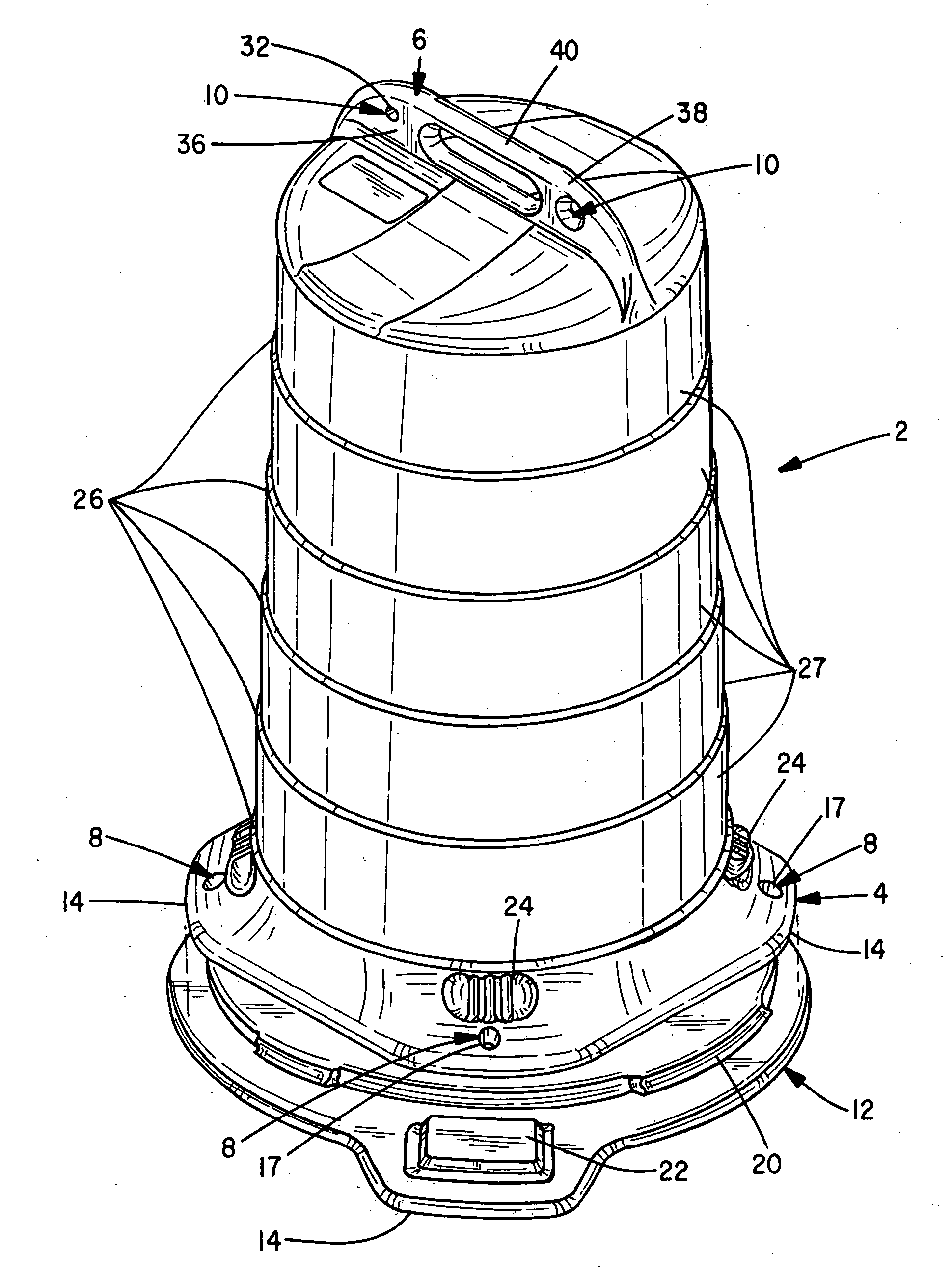
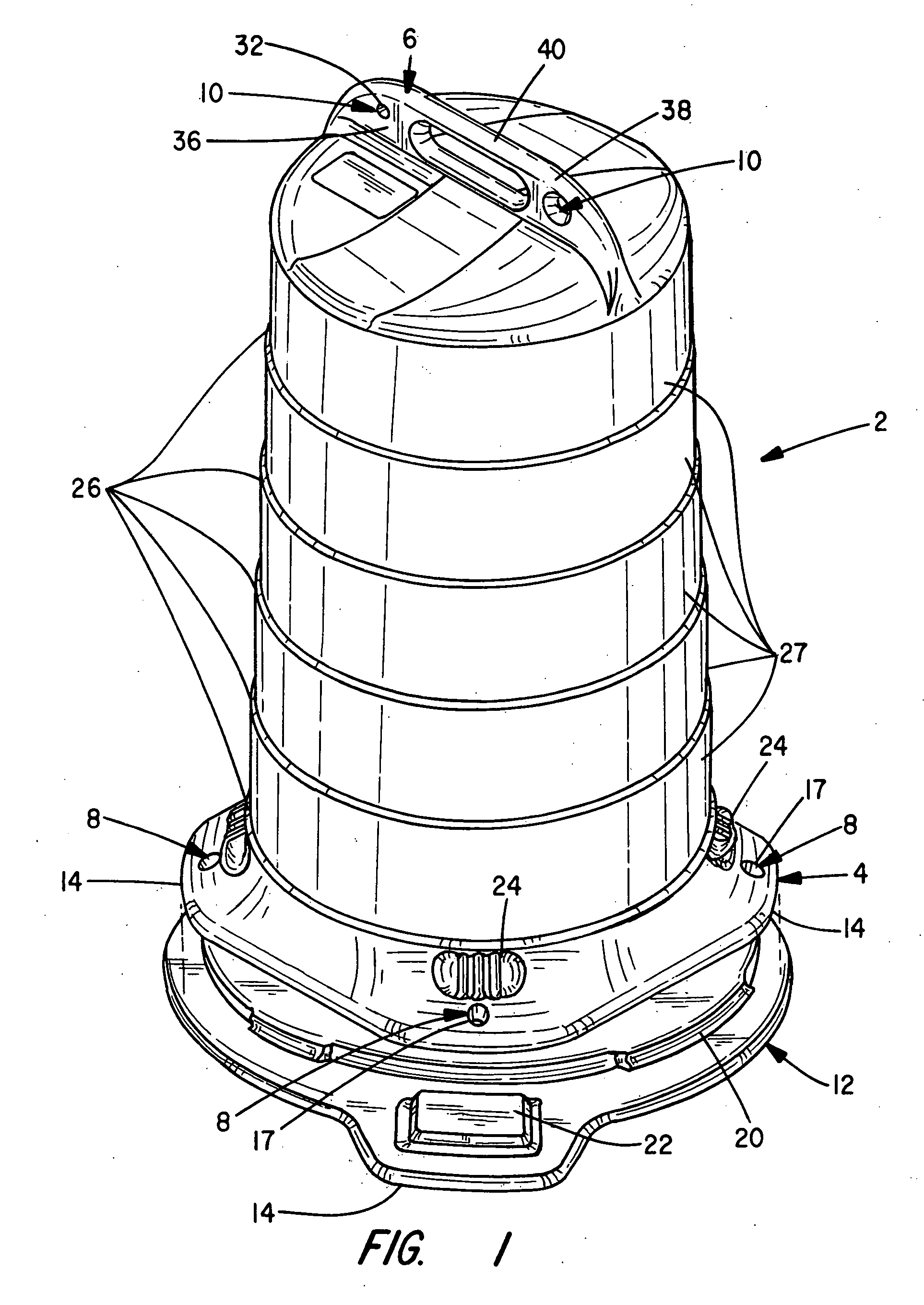
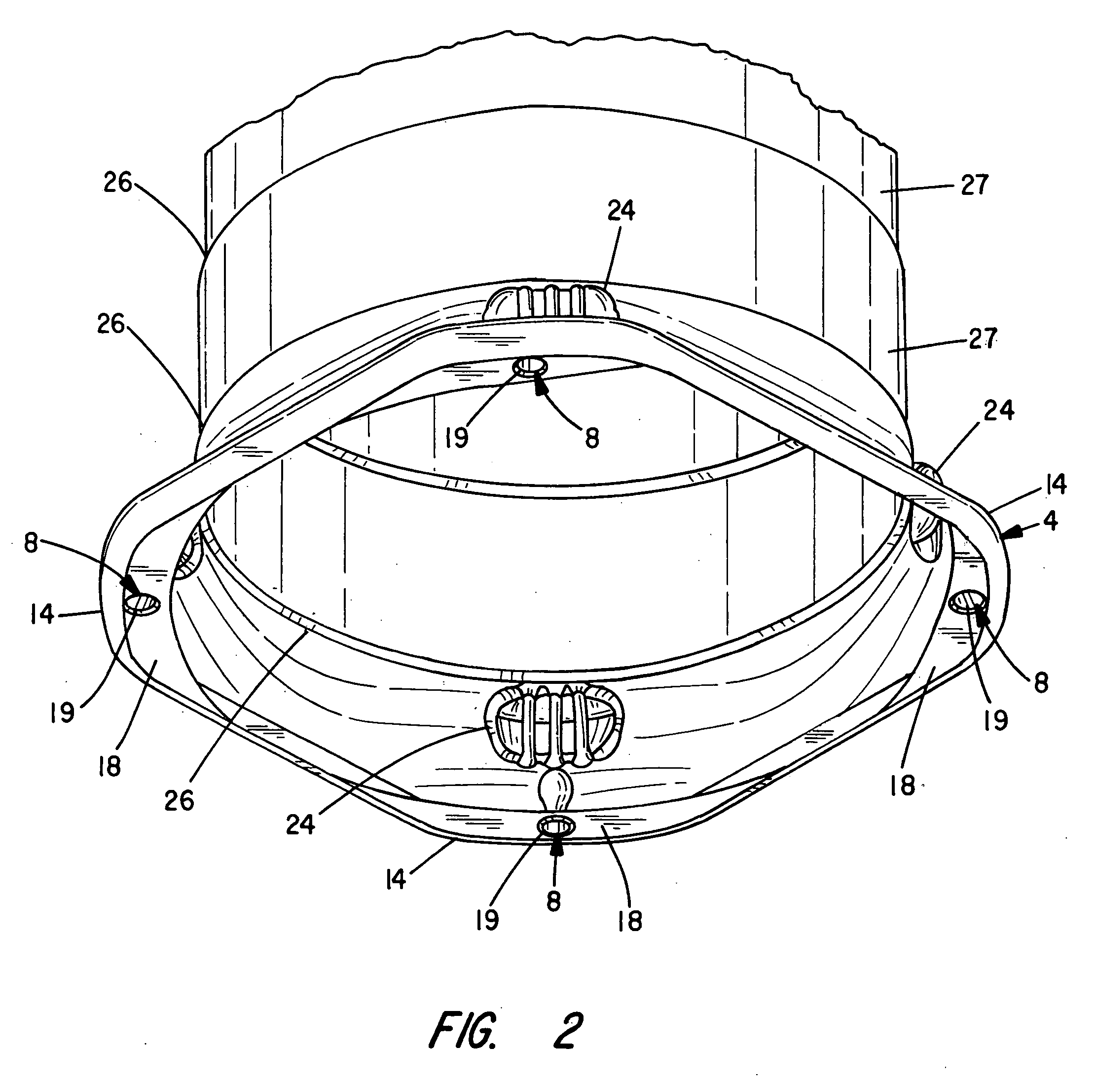
[0035]With attention to FIG. 1 a perspective view is shown to an improved traffic or work area delineator or barrel 2 of the invention. FIGS. 2 through 4 depict views to improvements to a base rim flange or skirt portion 4 of the barrel 2. FIGS. 5 through 7 depict views to improvements to a handle portion 6. The base flange and handle portions 4 and 6 each particularly include hollow, open ended struts or generally tubular pillars 8 and 10 that span between opposed or adjoining wall surfaces at regions exposed to high wear and tear. The pillars 8 and 10 strengthen the barrel 2 and maintain a desired separation between the mated wall surfaces.

[0036]The pillars 8 and 10 are formed from overlapping or generally parallel opposed walls surfaces that are depressed together and joined such as by thermal bonding or other welding methods. A hollow open-ended cavity is thus formed at each depressed wall surface. The locations of the pillars 8 and 10 are judiciously selected relative to points...


PUM

PropertyMeasurementUnit
diameteraaaaaaaaaa
thicknessaaaaaaaaaa
displacementaaaaaaaaaa

Abstract

A durable, single walled plastic traffic or work area delineator barrel. The single walled barrel is molded in a blow molding operation and handle and base rim flange regions of the barrel in one construction include compressed wall surfaces that define hollow, open-cavity pillars or struts that span between the walls. The pillars are constructed by depressing portions of the walls into contact and thermally bonding the materials together. In another construction corners of the base rim flange include recessed indentations and surface corrugations that are aligned to strengthen the rim flange.

Description

BACKGROUND OF THE INVENTION[0001]The present invention relates to traffic delineators and, in particular, to an improved barrel delineator constructed with a single wall and wherein high stress surfaces are strengthened with corrugated indentations or overlapped surfaces that are welded together during molding to form bonded pillars.[0002]A variety of permanent mount and portable devices exist for use in cordoning off work areas and / or controlling the flow of pedestrian and automotive traffic. Road striping, signage, lights, multi-section fence barricades and concrete safety barriers are a few of the most common devices seen daily on any roadway.[0003]Cones, barrels, folding stands and other portable devices are commonly used during short duration road repairs. One or more of these portable devices are typically distributed along a length of roadway to safely direct / re-direct traffic flow in relation to workmen, repair equipment and supply and material handling equipment and trucks....

Claims


Application Information

Patent Timeline
Patent Type & Authority Applications(United States)
IPC IPC(8): E01F9/012B29C49/42
CPCB29C49/00E01F9/0122E01F9/688E01F9/654
Inventor BROMM, SCOTTLECHNER, WILLIAM N.FISCH, ROBERT J.
Owner POLY FLEX INC
Learn More