Organic Light Emitting Diode
- Summary
- Abstract
- Description
- Claims
- Application Information
AI Technical Summary
Benefits of technology
Problems solved by technology
Method used
Image
Examples
first embodiment
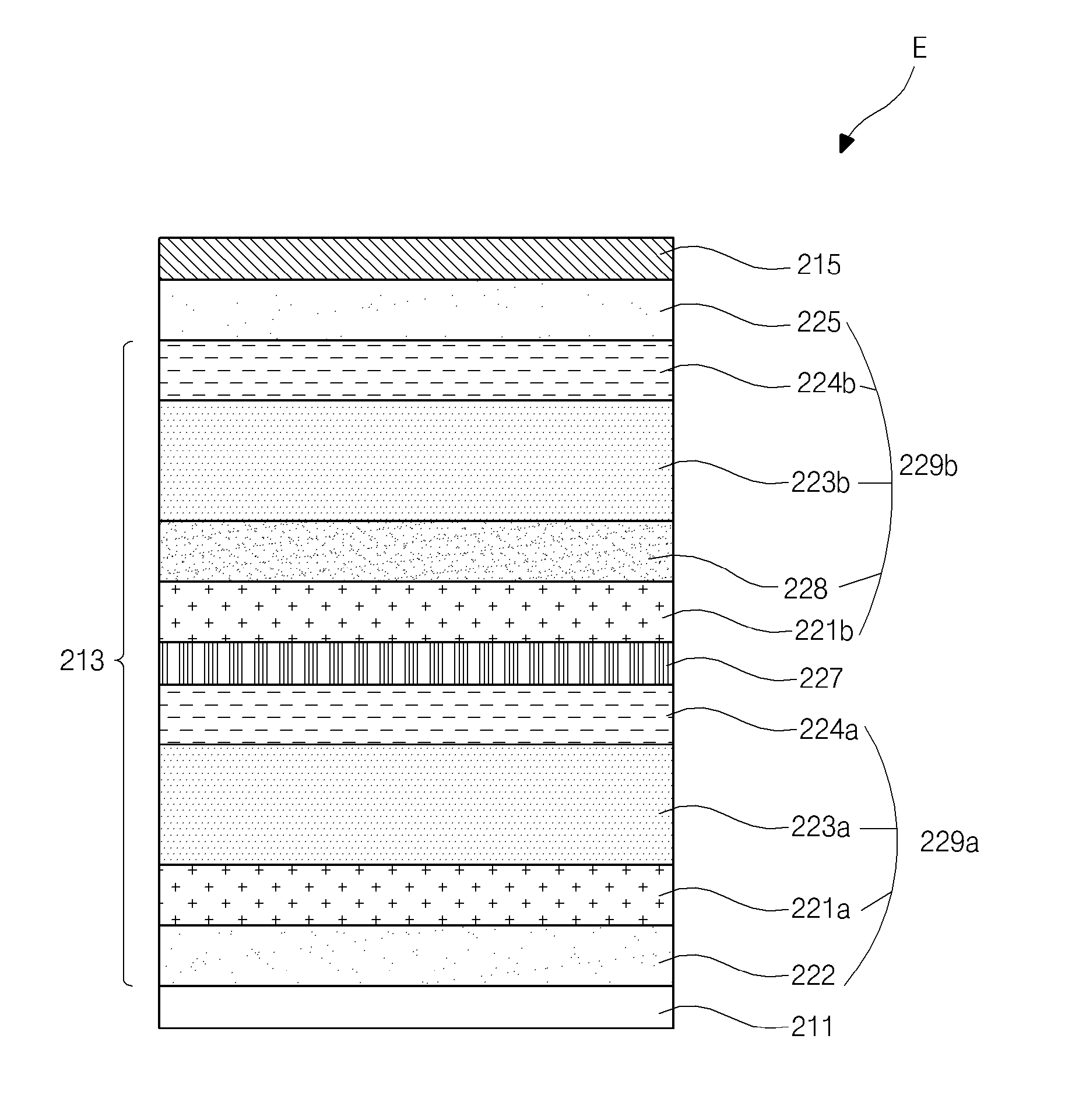
[0043]FIG. 4 is an energy band diagram showing an organic light emitting diode according to the present invention. For convenience of illustration, the first stack from FIG. 3 is shown but the second stack from FIG. 3 is omitted in FIG. 4.
[0044]In FIG. 4, the first EML 223a includes a single host 240 with a fluorescent dopant 250. A hole is injected from the first HTL 221a into the first EML 223a and an electron is injected from the first ETL 224a into the first EML 223a. After the hole and the electron form an exciton, a light corresponding to an energy difference between an excited state and a ground state is emitted as a visible ray when the exciton transitions from the excited state to the ground state.
[0045]Since an energy level of a LUMO of the dopant 250 of the first EML 223a is higher than an energy level of a LUMO of the host 240 of the first EML 223a, all or most of the hole from the first HTL 221a and the electron from the first ETL 224a can be injected into the host 240....
second embodiment
[0048]FIG. 6 is an energy band diagram showing an organic light emitting diode according to the present invention.
[0049]In FIG. 6, an EML 323a includes a single host 340 with first and second fluorescent dopants 350a and 350b. A hole is injected from an HTL 321a into the EML 323a and an electron is injected from an ETL 324a into the EML 323a. After the hole and the electron form an exciton, a light corresponding to an energy difference between an excited state and a ground state is emitted as a visible ray when the exciton transitions from the excited state to the ground state.
[0050]The first dopant 350a is formed to have an energy level of a LUMO higher than an energy level of a LUMO of the host 340, and the second dopant 350b is formed to have an energy level of a HOMO lower than an energy level of a HUMO of the host 340. In addition, one side portion of the EML 323a adjacent to the ETL 324a is doped with the first dopant 350a, and the other side portion of the EML 323a adjacent t...
third embodiment
[0052]FIG. 7 is an energy band diagram showing an organic light emitting diode according to the present invention.
[0053]In FIG. 7, an EML 423a includes first and second host 440a and 440b with first and second fluorescent dopants 450a and 450b. A hole is injected from an HTL 421a into the EML 423a and an electron is injected from an ETL 424a into the EML 423a. After the hole and the electron form an exciton, a light corresponding to an energy difference between an excited state and a ground state is emitted as a visible ray when the exciton transitions from the excited state to the ground state.
[0054]The first and second hosts 440a and 440b have different energy levels from each other. In addition, the first dopant 450a is formed to have an energy level of a LUMO higher than an energy level of a LUMO of the first host 440a, and the second dopant 450b is formed to have an energy level of a HOMO lower than an energy level of a HUMO of the second host 440b. Further, one side portion of...
PUM
 Abstract
Description
Claims
Application Information
 - R&D
- Intellectual Property
- Life Sciences
- Materials
- Tech Scout
- Unparalleled Data Quality
- Higher Quality Content
- 60% Fewer Hallucinations
Browse by: Latest US Patents, China's latest patents, Technical Efficacy Thesaurus, Application Domain, Technology Topic, Popular Technical Reports.
© 2025 PatSnap. All rights reserved.Legal|Privacy policy|Modern Slavery Act Transparency Statement|Sitemap|About US| Contact US: help@patsnap.com


