Wireless Network System, Method of Controlling the System, and Wireless Network Relay Device

a wireless network and wireless network technology, applied in active radio relay systems, location information based services, network topologies, etc., can solve the problems of increasing the data processing load imposed on the mobile wireless network relay device, the likelihood of degraded communication speed, and similar influences on other communications, so as to reduce the load on the mobile wireless, the effect of slow processing speed and small capacity

Inactive Publication Date: 2013-01-17
BUFFALO CORP LTD
View PDF0 Cites 8 Cited by
  • Summary
  • Abstract
  • Description
  • Claims
  • Application Information

AI Technical Summary

Benefits of technology

[0008]With the configuration described above, a download request from a client requesting download is received in the mobile wireless access point and is transmitted to the fixed wireless access point when the mobile wireless access point and the fixed wireless access point are connected to each other. The fixed wireless access point downloads the file based on the received request requesting downloading, and sends the downloaded file to the mobile wireless access point. Thus, since the fixed wireless access point executes the file downloading, files may be downloaded while increased load on the mobile wireless access point is kept to a minimum. Further, since increased load on the mobile wireless access point may be held to a minimum, built-in resources (e.g., CPU and memory) in the device itself can be made lower-level performance components (a CPU of slower processing speed and memory of smaller capacity). Therefore, it is possible to reduce the size and production cost of the mobile wireless access point. Furthermore, the downloaded file is stored in the file storage unit disposed in the mobile wireless access point. Therefore, when the mobile wireless access point is detached from the fixed wireless access point or in a like situation, the file downloaded by the fixed wireless access point can be presented to the client from the mobile wireless access point.
[0038]In the configuration described above, a download request from a client is received in the fixed wireless access point via the mobile wireless access point. Further, in the fixed wireless access point, files are downloaded and sent to the mobile wireless access point based on the received download request. Thus, since file downloading is executed in the fixed access point, the downloading of files with minimal increase in load on the mobile wireless access point can be realized. Further, the fact that increase in load on the mobile wireless access point is controlled to a minimum means that resources (the CPU and memory, for example) of lower-level performance (a CPU of slower processing speed and memory of smaller capacity) can be built into the mobile wireless access point. This in turn enables the mobile wireless access point to be smaller in size and lower in production cost. Furthermore, inasmuch as the downloaded file is sent to the mobile wireless access point, the downloaded file for the client can be presented to the client from the mobile wireless access point when the mobile wireless access point is detached from the fixed wireless access point, or in a like situation, provided that the mobile wireless access point is capable of storing the downloaded file therein.

Problems solved by technology

Consequent problems with obtaining (i.e., downloading) files stored in a server on the Internet via a mobile wireless network relay device have been prolonged file-downloading times, substantially reducing the remaining battery capacity of the mobile wireless network relay device, and increased data-processing loads imposed on the mobile wireless network relay device by the file downloading.
Consequently, when the mobile wireless network relay device handles other communications different from file downloading, there is a likelihood of degraded communication speed and similar influences on the other communications.

Method used


Image

  • Wireless Network System, Method of Controlling the System, and Wireless Network Relay Device
  • Wireless Network System, Method of Controlling the System, and Wireless Network Relay Device
  • Wireless Network System, Method of Controlling the System, and Wireless Network Relay Device

Examples


first embodiment

A. First Embodiment

A1. System Configuration

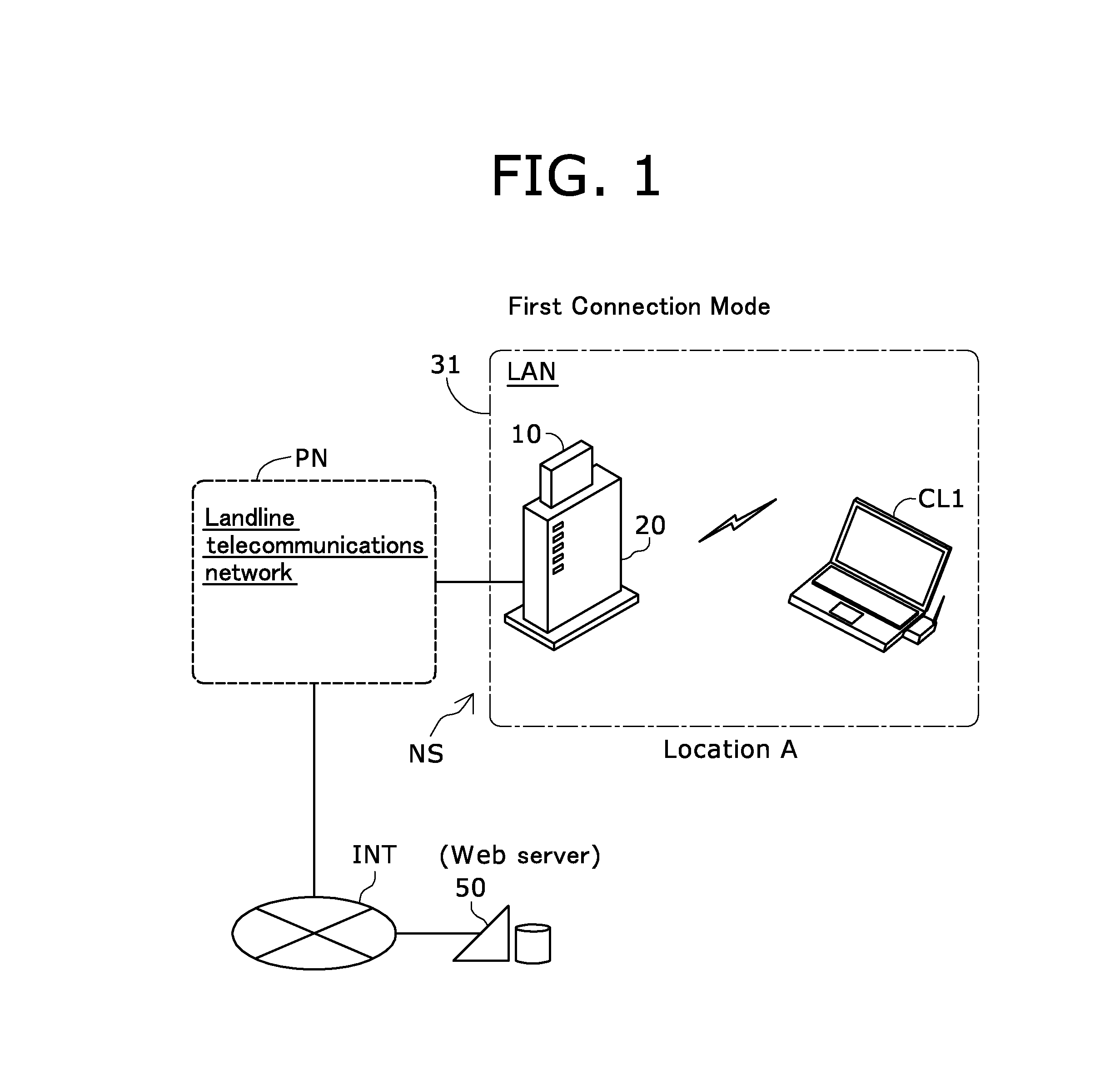
[0056]FIG. 1 is a simplified explanatory diagram illustrating the configuration of a wireless network system as one embodiment of the present invention. A wireless network system NS includes a home gateway 20 and a mobile access point 10. The wireless network system NS is a system for connecting a client CL1 to the Internet INT. Via the wireless network system NS and Internet INT, the client CL1 can download files stored in a server 50.

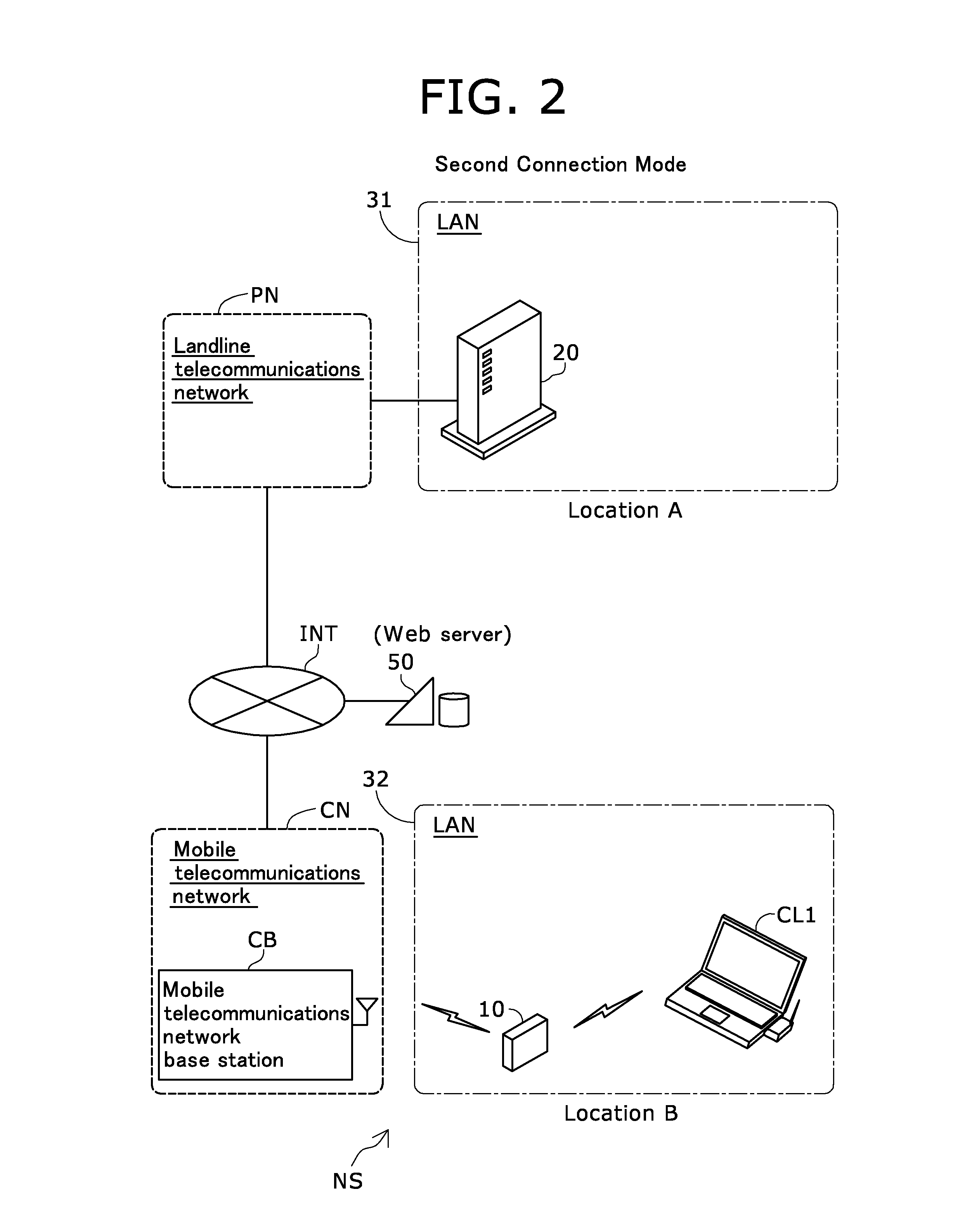
[0057]The wireless network system NS has a plurality of connection modes relating to the home gateway 20 and the mobile access point 10. In the connection mode (a first connection mode) illustrated in FIG. 1, the home gateway 20 is connected to the Internet INT via a landline (i.e., wired) communications network PN (e.g., optical lines employing optical fiber, asymmetric digital subscriber lines (ADSLs) employing metallic cable). In the first embodiment, the mobile access point 10 is physically connected to (...

second embodiment

B. Second Embodiment

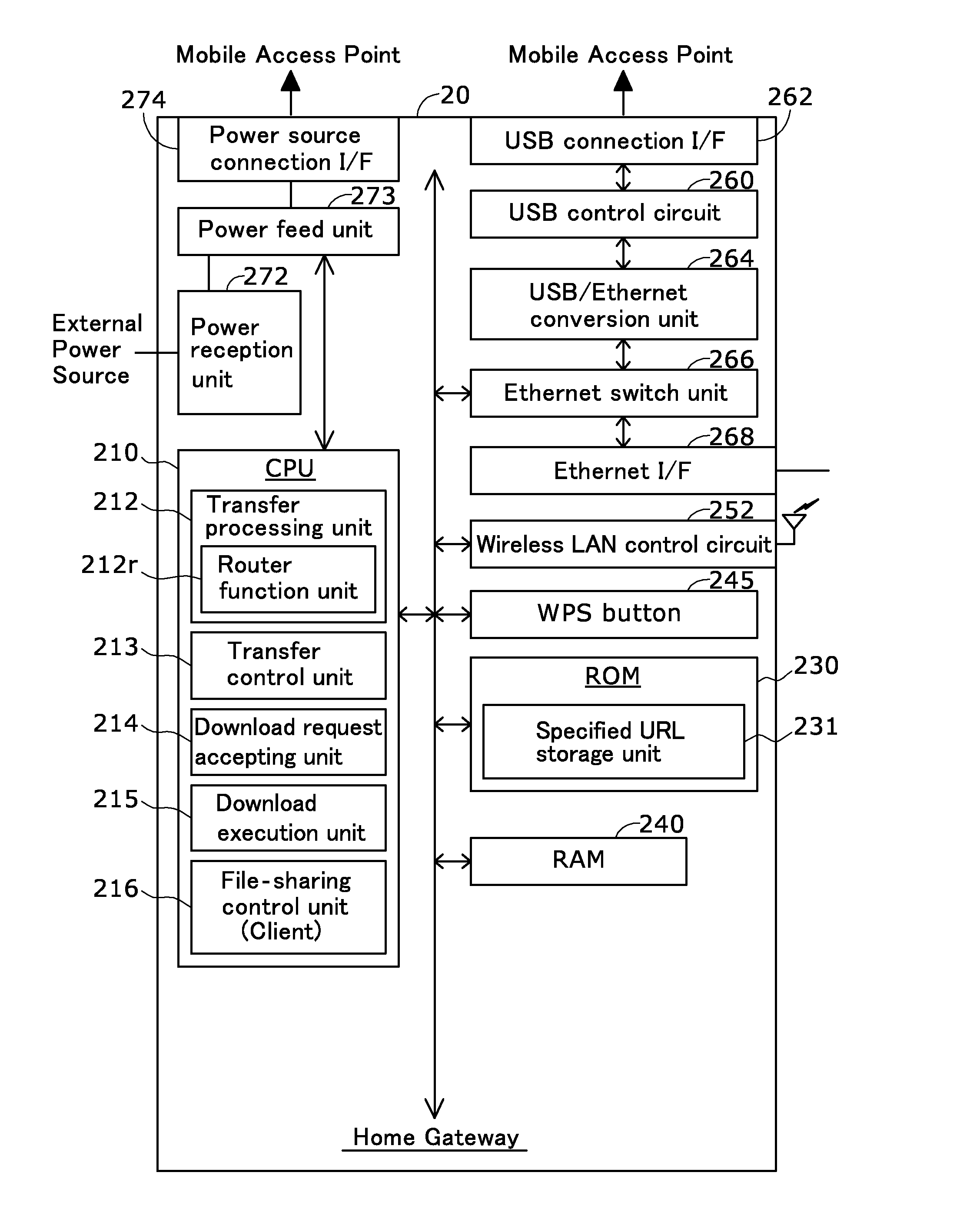
[0107]FIG. 8 is a block diagram illustrating configurational details of a mobile access point of a second embodiment. FIG. 9 is a block diagram illustrating configurational details of a home gateway of the second embodiment. The mobile access point 10a illustrate in FIG. 8 is different from the mobile access point 10 of the first embodiment shown in FIG. 3, where the former is configured to include a CPU 110 that has no functionality of a connection monitor unit. Otherwise, the configuration of the mobile access point 10a is the same as that of the mobile access point 10 of the first embodiment. The home gateway 20a illustrated in FIG. 9 is different from the home gateway 20 of the first embodiment shown in FIG. 4, where the former is configured to include a CPU 210 that functions as a connection monitor unit 217. Otherwise, the configuration of the home gateway 20a is the same as the home gateway 20 of the first embodiment.

[0108]FIG. 10 is a sequence chart repre...

third embodiment

C. Third Embodiment

[0115]FIG. 11 is a flowchart representing procedural flows in a download request accepting process in a third embodiment. A wireless network system of the third embodiment is different from the wireless network system NS of the first embodiment where the former is configured to download a file at the mobile access point 10 if a predetermined condition is satisfied in the second connection mode. Otherwise, the configuration of the wireless network system of the present embodiment is the same as that of the wireless network system NS of the first embodiment.

[0116]As shown in FIG. 11, the download request accepting process of the third embodiment is different from the download request accepting process of the first embodiment shown in FIG. 5 where the former is configured to carry out additional steps S120 through S145 and is otherwise the same as the first embodiment.

[0117]At the mobile access point 10, when a URL included in the download request is stored in the de...


PUM


Abstract

Wireless network system including mobile and fixed wireless access points. The access points each include a connection unit for connecting to the partner access point and enabling communications between them. The mobile access point has a download-request accepting unit, and a download-request transmitting unit that transmits an accepted download request conditional upon both the access points being connected to each other via the mobile access point's connection unit. The fixed access point has a download-request receiving unit that receives download requests when transmitted from the mobile access point via the fixed access point's connection unit, and has a file acquisition unit that in response to a thus-received download request downloads the file via the fixed access point's communications network. A file transmitting unit in the fixed access point transmits the thus-downloaded file to the mobile access point via the fixed access point's connection unit.

Description

BACKGROUND OF THE INVENTION[0001]1. Technical Field[0002]The present invention relates to techniques for downloading files via wireless network relay devices.[0003]2. Description of the Related Art[0004]Wireless local area network (LAN) access points (also referred to simply as “access points” hereinafter) are widely used in homes and offices for connecting wireless LAN clients (also referred to simply as “clients” hereinafter) such as personal computers (PCs) and game machines to a network. Utilized as the access points are compact, lightweight devices (also referred to as “mobile wireless network relay device” hereinafter) that excel in portability and connect to mobile telecommunications networks such as a third-generation (3G) / High Speed Packet Access (HSPA) line, instead of landline communications networks. Using the mobile wireless network relay device enables a client to connect to the Internet in locations (such as outdoors, for example) where no fixed wireless network relay...

Claims


Application Information

Patent Timeline
Patent Type & Authority Applications(United States)
IPC IPC(8): H04W88/04
CPCH04W84/12H04W4/02H04L67/06H04W88/04
Inventor HABA, YOSHIFUMI
Owner BUFFALO CORP LTD
Why Eureka
Try Eureka