Wet Flue Gas Desulfurization Device

Inactive Publication Date: 2013-01-24
BABCOCK HITACHI KK
View PDF3 Cites 7 Cited by
  • Summary
  • Abstract
  • Description
  • Claims
  • Application Information

AI Technical Summary

Benefits of technology

[0026]According to the invention configured thus, it is possible to provide a wet flue gas desulfurization device by whi

Problems solved by technology

Thus, there is a problem that satisfactory gas-liquid contact is not performed partially so that the performance to absorb sul

Method used


Image

  • Wet Flue Gas Desulfurization Device
  • Wet Flue Gas Desulfurization Device
  • Wet Flue Gas Desulfurization Device

Examples


Embodiment Construction

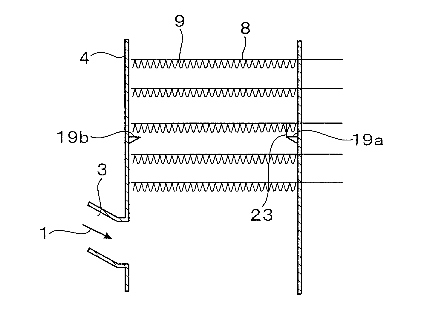
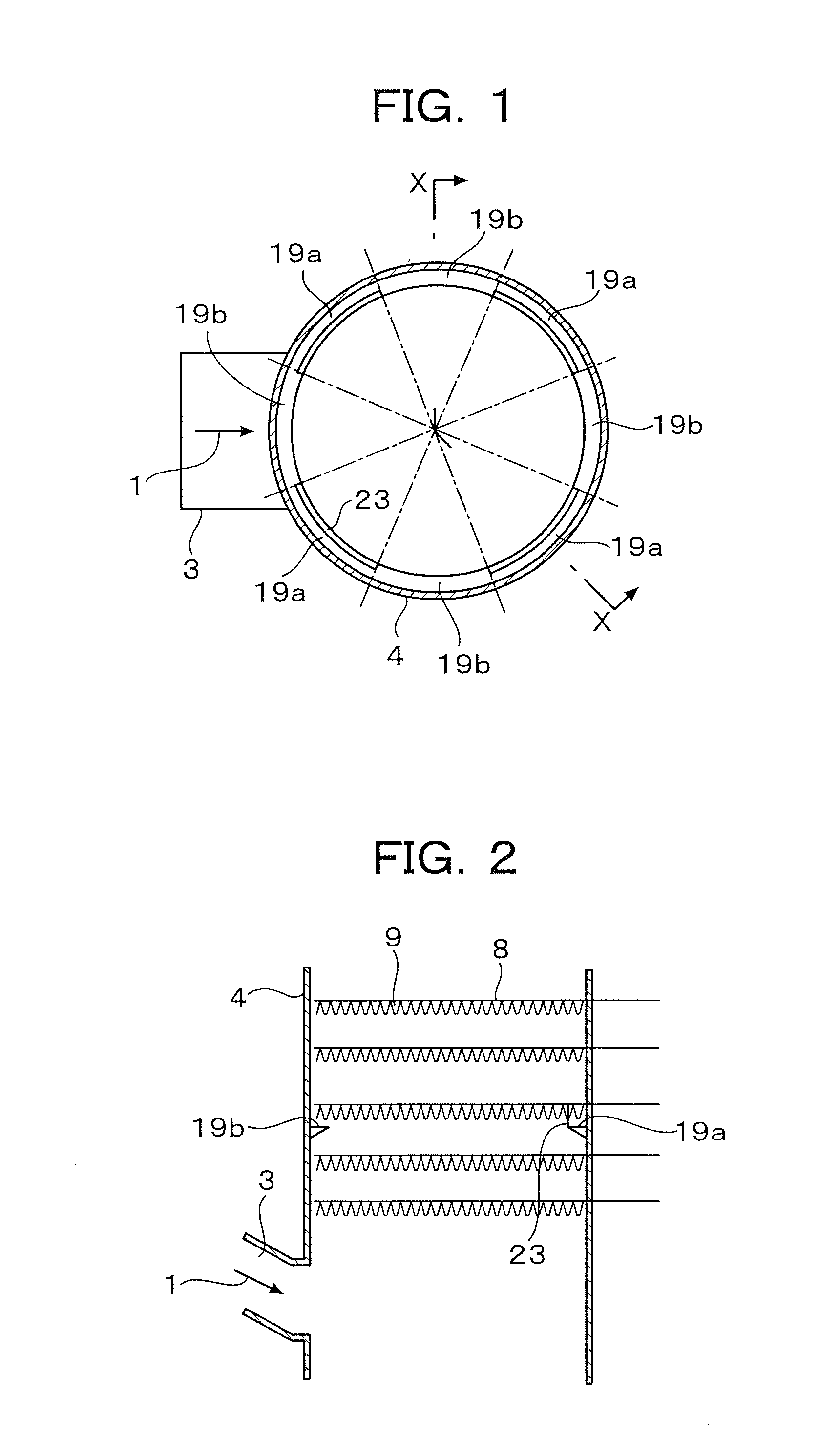
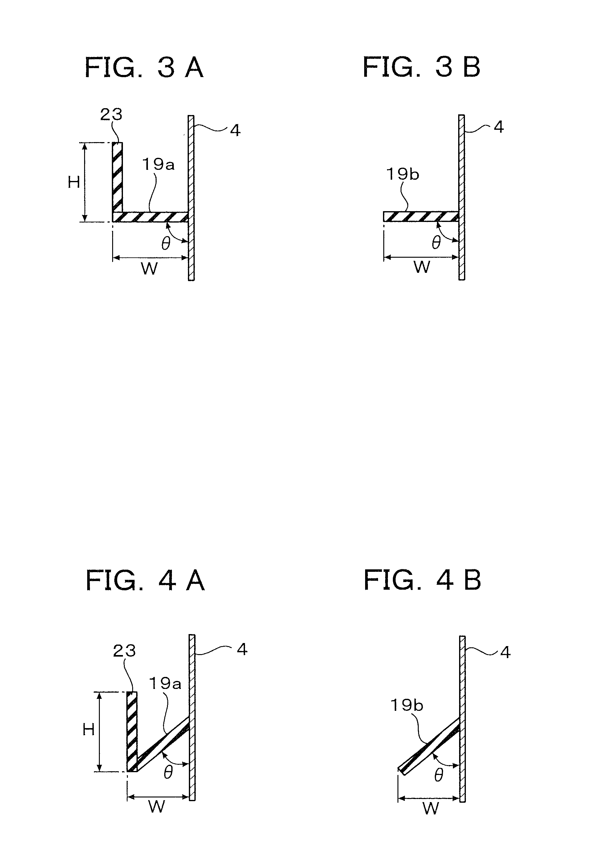
[0051]Each of the first to fifth configurations of the invention which will be described below is aimed at a wet flue gas desulfurization device as a means for removing sulfur oxide contained in exhaust gas discharged from a boiler or the like installed in a thermal power plant, a factory or the like. The wet flue gas desulfurization device is configured in such a manner that a gas inlet portion for introducing exhaust gas is formed in a sidewall of an absorber, spray headers for spraying an absorption liquid to the exhaust gas rising inside the absorber from the gas inlet portion are provided in multiple stages so as to extend along the gas flow direction, and a gas blow-out (gas short pass) prevention member is placed along an entire circumference of an inner surface of the sidewall of the absorber above the gas inlet portion.

[0052]The first configuration of the invention is characterized in that portions provided with dams and portions provided with no dams are disposed alternate...


PUM

PropertyMeasurementUnit
Lengthaaaaaaaaaa
Circumferenceaaaaaaaaaa

Abstract

A wet flue gas desulfurization device includes, an absorber provided with: a absorber tank provided at a lower part of the absorber so as to store an absorption liquid; an absorption portion provided above the absorber tank and having multiple stages of spray headers for spraying the absorption liquid; an absorption liquid circulation system for circulating the absorption liquid in the absorber tank to the spray headers; an exhaust gas inlet portion provided in a sidewall between the absorber tank and the absorption portion; and a gas blow-out prevention member provided along an entire circumference of an inner surface of the sidewall between the exhaust gas inlet portion and the uppermost-stage spray header. Dams are intermittently provided at an inner peripheral end of the gas blow-out prevention member to extend along a circumferential direction thereof.

Description

TECHNICAL FIELD[0001]The present invention relates to a flue gas treatment device for purifying flue gas of fuel discharged from a combustion device such as a boiler installed in a thermal power plant, a factory, etc. Particularly, it relates to a wet flue gas desulfurization device for reducing acidic gas such as sulfur oxide, hydrogen chloride, hydrogen fluoride, etc. or dust and soot contained in flue gas, and substances such as minor components contained in fuel.BACKGROUND ART[0002]FIG. 22 shows a general system of a wet flue gas desulfurization device in a thermal power plant.[0003]In FIG. 22, exhaust gas 1 discharged from a boiler or the like installed in a thermal power plant, a factory or the like is introduced into an absorber 4 from a gas inlet portion 3. The absorber 4 is chiefly constituted by an absorber tank 5 located in a lower part of the absorber and an absorption portion 6 located in an upper part of the absorber. The opening of a slurry flow rate control valve 16 ...

Claims


Application Information

Patent Timeline
IPC IPC(8): B01D53/18
CPCB01D3/008B01D53/504F23J2219/40F23J15/04F23J2215/20B01D53/78B01D53/50B01D53/18B01D53/14
Inventor MURAMOTO, TAKASHIMORI, SHOGONOSAKA, HIROYUKINAKAMOTO, TAKANORI
Owner BABCOCK HITACHI KK
Why Eureka
Try Eureka