
Multi-Mode Electric Vehicle Charging Station

a charging station and multi-mode technology, applied in charging stations, electric vehicle charging technology, transportation and packaging, etc., can solve the problems of not all chargers are compatible, equipment costs, operational logistics, and responsiveness to customer requests, so as to reduce the cost of charging equipment, save space and equipment costs, and be easily installed

Inactive Publication Date: 2013-01-24
GREEN CHARGE NETWORKS
View PDF9 Cites 209 Cited by
  • Summary
  • Abstract
  • Description
  • Claims
  • Application Information

AI Technical Summary

Benefits of technology

The patent describes a way to use a DC bus already present in a standard AC-DC inverter used for EV charging to reduce costs of charging equipment. The controller ensures that the output at the DC bus is compatible with both DC and AC charging protocols, allowing for both AC and DC charging of EVs. This results in cost savings and space benefits, especially in roadside assistance scenarios where smaller equipment can be easily installed on a service vehicle.

Problems solved by technology

At least one of these standardized ports can be found on most production EVs, but not all chargers are compatible with each standard.
Most of the time this poses a minor inconvenience to EV drivers, since they can plan routes around known locations of chargers that are compatible with their EVs, but at times the EV drivers are unable to reach a compatible charger and roadside assistance is needed to tow the EV or to provide some charge to the EV battery to allow it to reach another charging station.
Unfortunately, roadside service providers must be able to provide separate sets of charging equipment that comply with multiple charging standards in order to serve a variety of EVs.
Equipment costs, operational logistics, and responsiveness to customer requests all suffer due to the randomness inherent in the location and charger compatibilities of the EVs in need of assistance.

Method used


Image

  • Multi-Mode Electric Vehicle Charging Station
  • Multi-Mode Electric Vehicle Charging Station
  • Multi-Mode Electric Vehicle Charging Station

Examples


Embodiment Construction

[0022]While preferable embodiments of the invention have been shown and described herein, it will be obvious to those skilled in the art that such embodiments are provided by way of example only. Numerous variations, changes, and substitutions will now occur to those skilled in the art without departing from the invention. It should be understood that various alternatives to the embodiments of the invention described herein may be employed in practicing the invention. It shall be understood that different aspects of the invention can be appreciated individually, collectively, or in combination with each other.

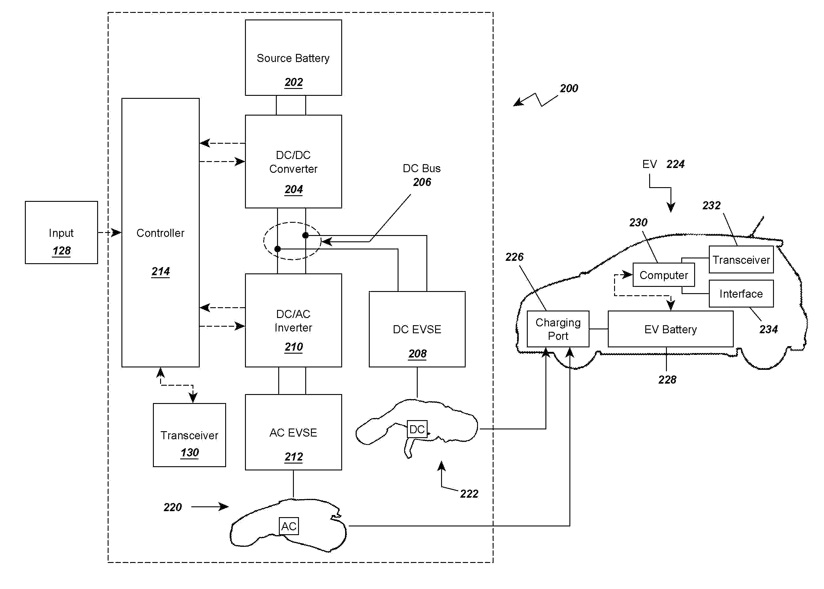
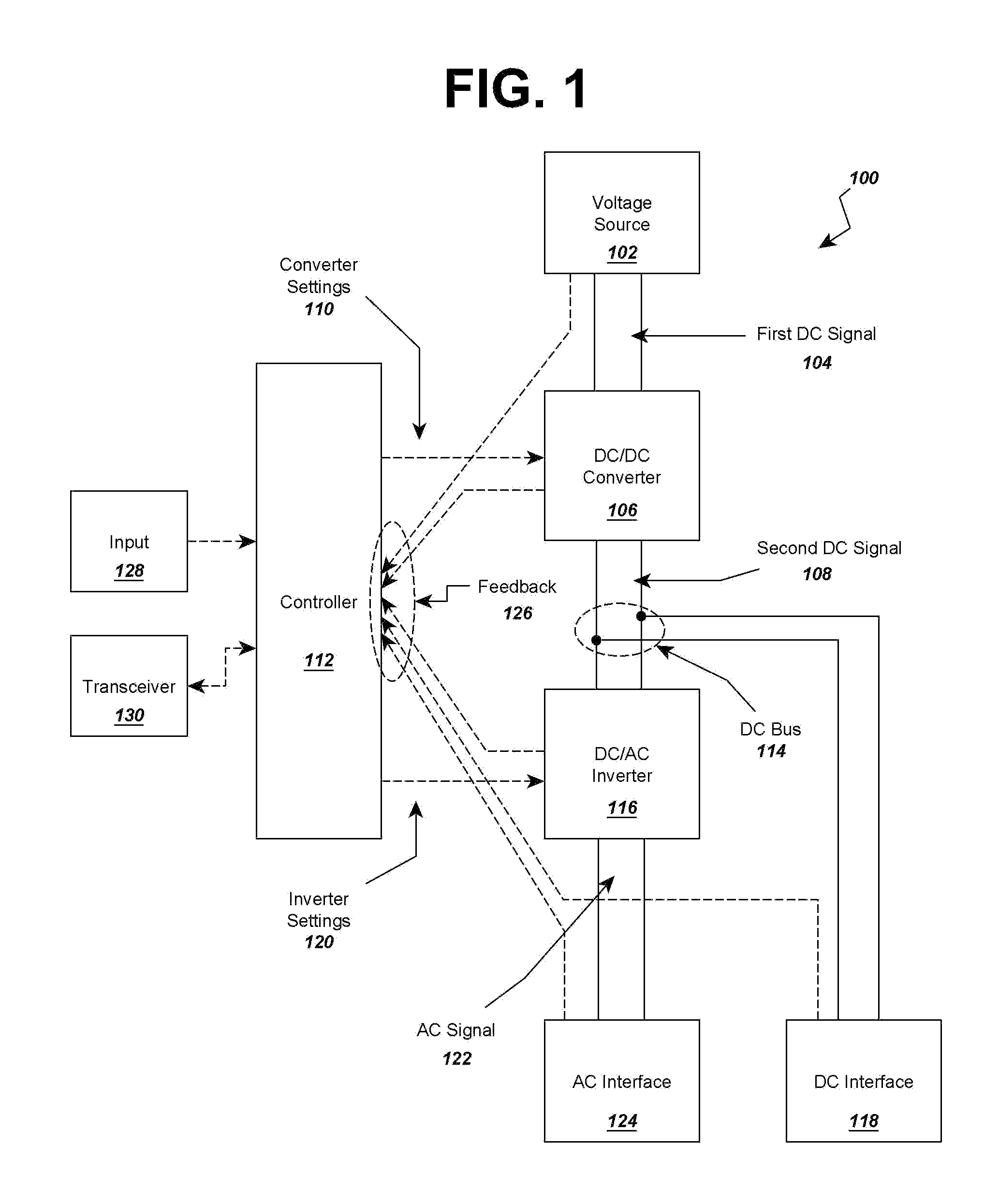
[0023]Turning now to the figures in detail, FIG. 1 shows an insertion block diagram of a circuit of an EV charging station 100. A voltage source 102 has a first DC signal 104 that is electrically connected to a DC to DC converter 106. The DC to DC converter 106 converts the first DC signal 104 to a second DC signal 108 according to converter settings 110 provided by a controlle...


PUM


Abstract

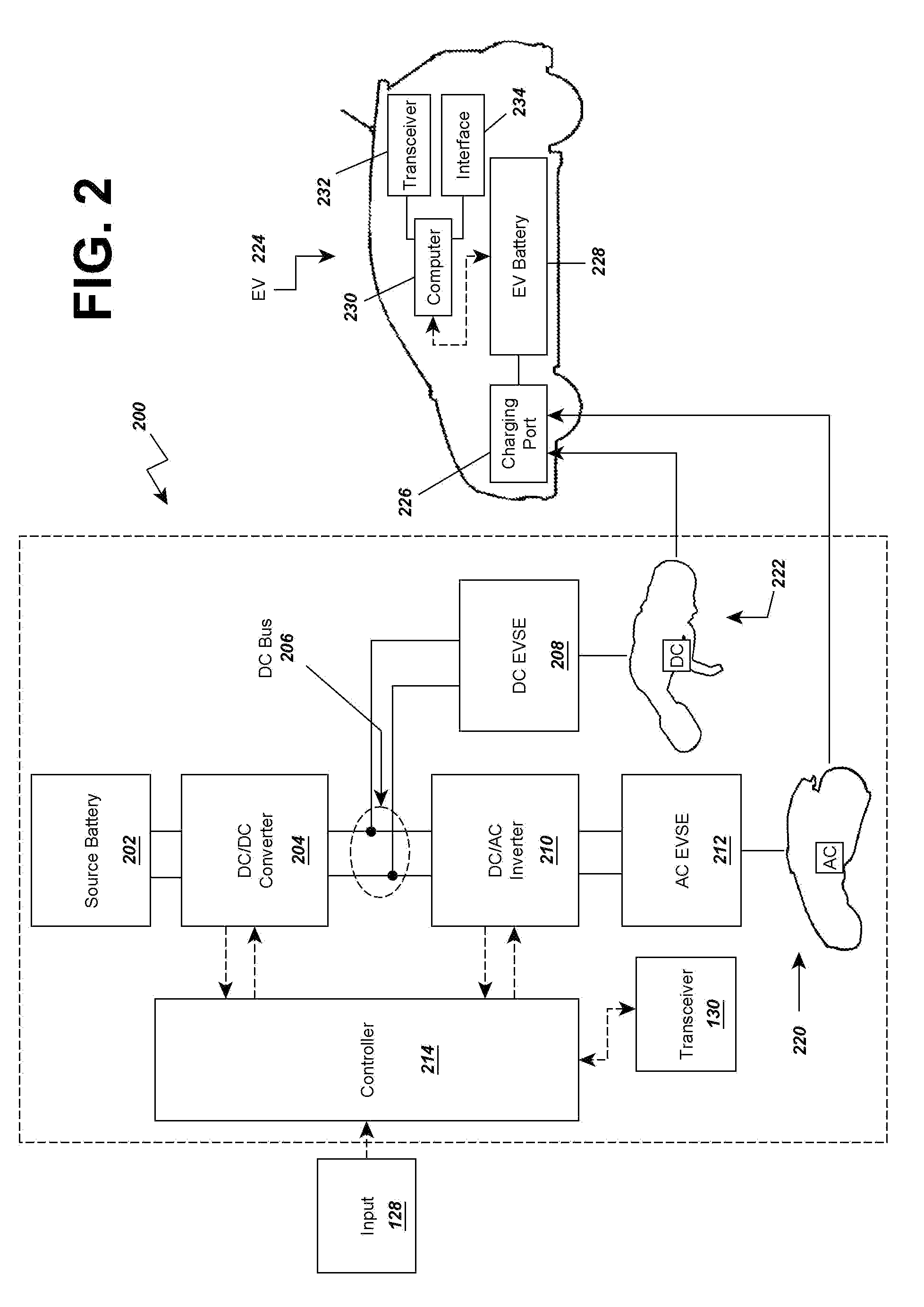
A reduced size and complexity multi-mode electric vehicle charging station is provided which allows a user to select AC and DC powerform output and may provide those outputs to connectors for charging electric vehicles. A voltage source is provided to a DC converter that then outputs to a DC bus or electrical connection. The DC bus may be accessed by DC charging equipment or a DC-AC inverter that is connected to AC charging equipment, thereby providing DC and AC charging ability. In one aspect, the multi-mode electric vehicle charging station is used in a rescue vehicle for charging stranded EVs via multiple charging standards without requiring the rescue vehicle to carry independent charging systems for each charging standard. In another aspect, the charging station is used in a stationary charging station to reduce cost and complexity of using multiple independent charging systems.

Description

CROSS REFERENCE TO RELATED APPLICATIONS[0001]Priority is claimed to the following related pending U.S. Provisional Patent Application, which is hereby incorporated by reference in its entirety: Ser. No. 61 / 509,010, filed Jul. 18, 2011.BACKGROUND[0002]The present invention relates to the fields of electric vehicle charging systems, electric vehicle charging protocols, electric vehicle charging systems that implement multiple charging standards, and related fields.[0003]In recent years, the popularity and affordability of electric vehicles (EVs) such as battery-powered EVs (BEVs) and hybrid gasoline-electric EVs (HEVs) has grown dramatically. In many cases, the batteries of these vehicles require periodic recharging to keep them in motion. Industry leaders have recognized this need and have identified and implemented a number of charging protocol standards, such as, for example, the Society of Automotive Engineers (SAE) J1772 AC “Level 2” charging standard or the TEPCO® CHAdeMO® DC “q...

Claims


Application Information

Patent Timeline
IPC IPC(8): H02J7/00
CPCH02J7/0027Y04S30/14Y02T10/7005Y02T90/121Y02T90/14Y02T10/7055B60L11/1818B60L11/1846B60L11/185B60L2200/36B60L2210/10B60L2210/30B60L2210/40B60L2250/16Y02T10/7241Y02T10/7216Y02T90/169Y02T90/128Y02T90/127H02J7/0055Y02T10/7072B60L53/16B60L53/65B60L53/11H02J2207/40H02J7/00045Y02T10/70Y02T10/72Y02T90/12Y02T90/167H02J7/0013H02J7/0042H02J2310/48
Inventor TADDEO, STEPHEN R.EDGAR, DAVID L.PROSSER, RONALD D.
Owner GREEN CHARGE NETWORKS
Learn More