
Fault wave arrival determination

Active Publication Date: 2013-01-24
HITACHI ENERGY SWITZERLAND AG
View PDF2 Cites 42 Cited by
  • Summary
  • Abstract
  • Description
  • Claims
  • Application Information

AI Technical Summary

Benefits of technology

The invention improves accuracy by accurately identifying the time of a fault wave, which is useful when a fault occurs near the end of a long power line. It also eliminates the need for special satellite synchronized clocks to time stamp external events. Instead, more general purpose satellite synchronized clocks can be used, which will not be dedicated to the fault wave arrival time determination.

Problems solved by technology

In power transmission systems, faults like ground faults may occur.
This type of distance to fault determination functions well in relation to AC power lines, but is less suitable for Direct Current (DC) power lines.
There is one problem with this approach though and that is that the amplitude and shape of the fault wave that arrives at a measurement point can vary considerably based on where the fault occurs in relation to this measurement point.
This has a negative influence on the accuracy of the measurement of the arrival time.
It is therefore in some situations hard to determine the point in time that such a fault wave actually reaches a measurement point.
Furthermore, as the distance to a fault is determined through a difference between two such arrival times, it is sufficient that one of the measurements is not precise enough in order to degrade the accuracy of the determination of the distance.

Method used


Image

  • Fault wave arrival determination
  • Fault wave arrival determination
  • Fault wave arrival determination

Examples


Embodiment Construction

[0023]In the following, embodiments of the invention providing the above described functionality will be described.

[0024]The present invention is directed towards providing an apparatus in a power transmission system, i.e. in a system for the transmission of electrical power. This system can for instance be a High Voltage Direct Current system (HVDC) or some types of Flexible Alternating Current Transmission System (FACTS) such as Series Capacitors or controlled series capacitors.

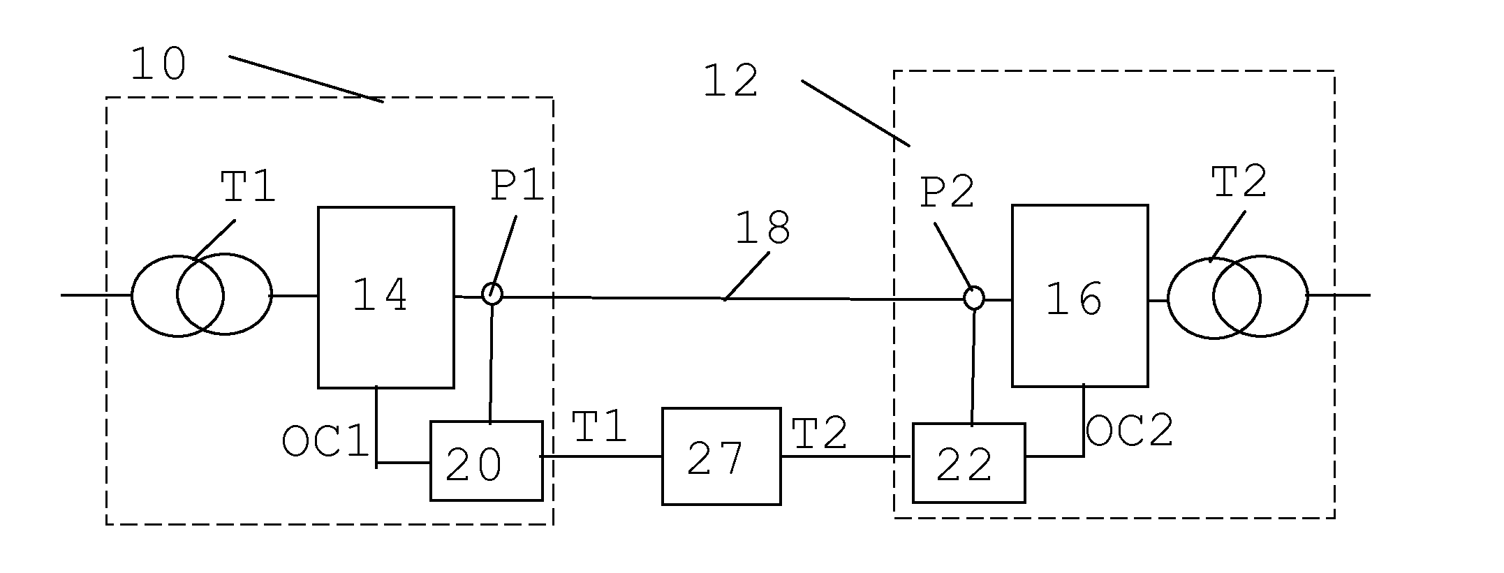
[0025]In FIG. 1 there is schematically shown an HVDC system for connection between two Alternating Current (AC) power transmission systems. For this reason the HVDC system includes a first and a second substation 10 and 12, where the first substation 10 includes a first transformer T1 and a first set of converters 14 for conversion between AC and DC, which first set of converters 14 may provide a rectifier. The first transformer T1 connects the first set of converters 14 to the first AC power transmission s...


PUM


Abstract

A method and apparatus for determining the time of arrival of a fault wave at a measurement point of a power transmission system includes a measurement unit measuring a power quantity of the system at the measurement point (P1) for obtaining a measurement quantity being a potential fault wave, a time keeping unit, a storage unit storing the measurement quantity, a comparing unit comparing the measurement quantity with a threshold (T1) for detecting the presence of a fault wave (W1) and an analyzing unit. The analyzing unit analyzes measurements made before the fault wave presence was detected, determines the starting point (SP) of the fault wave based on the analysis and sets the time of the starting point to be the fault wave arrival time (T1).

Description

FIELD OF THE INVENTION[0001]The present invention generally relates to power transmission systems. More particularly the present invention relates to a method and an apparatus for determining the time of arrival of a fault wave at a measurement point of a power transmission system.BACKGROUND[0002]In power transmission systems, faults like ground faults may occur. It is important to locate where such a fault occurs for instance in order to quickly remove it.[0003]For long power lines, like overhead lines and cables, it is desirable to detect the location of a ground fault directly after the fault occurs in order to be able to dispatch repair crews to the correct position of the line or cable. Such power lines can be very long, for instance in range of 700-2500 km for overhead lines or in the range of 100-1000 km for submarine cables. Also combinations of overhead lines and cables are possible.[0004]It is possible to determine the distance to a fault through analyzing a wave caused by...

Claims


Application Information

Patent Timeline
IPC IPC(8): G01R31/08
CPCG01R31/088G01R31/085
Inventor BJORKLUND, HANS
Owner HITACHI ENERGY SWITZERLAND AG
Learn More