Screw

a screw and screw technology, applied in the field of screws, can solve the problems of lowering the locking velocity and failing to smoothly carry out the locking of the screw, and achieve the effect of lowering the resistance and carrying out the locking smoothly and quickly

Inactive Publication Date: 2013-01-24
YIH SHWEI BOLT INDAL
View PDF23 Cites 6 Cited by
  • Summary
  • Abstract
  • Description
  • Claims
  • Application Information

AI Technical Summary

Benefits of technology

[0006]The objective of this invention is to offer a screw, able to lower resistance when the screw is being locked into a wood piece for enabling the screw to carry out locking smoothly and quickly.
[0007]The screw in the present invention has the circumference of a head provided thereon with continuously arranged dot-shaped ribs for carrying out point contact, not surface contact, between the ribs and the walls of excavated holes of a wood piece, able to lower locking resistance.

Problems solved by technology

That is to say, when the head 10 of the screw 1 is being locked and embedded into a wood piece (A), the linear ribs 12 will contact with the hole wall AO of the wood piece (A), as shown in FIG. 3, and produce too large a locking resistance, thus failing to smoothly carry out locking of a screw and hence lowering locking velocity.

Method used


Image

  • Screw
  • Screw
  • Screw

Examples


Embodiment Construction

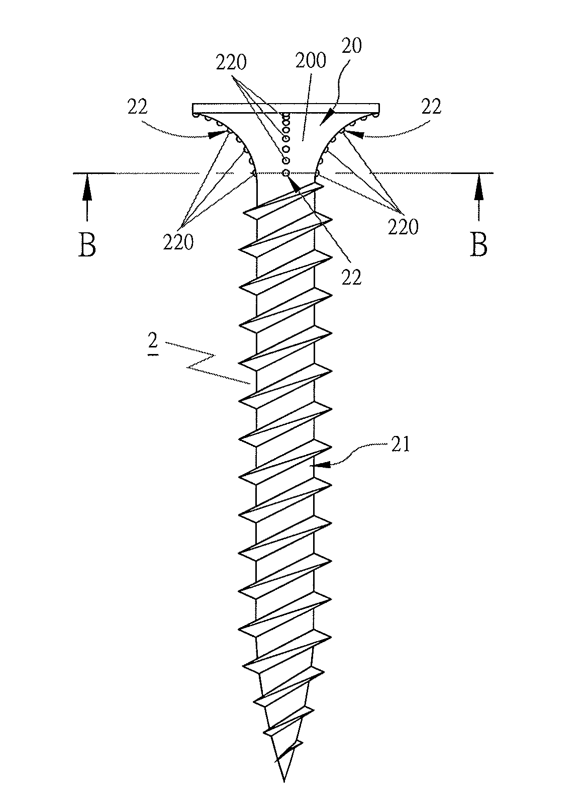
[0020]A preferred embodiment of a screw 2 in the present invention, as shown in FIGS. 4-5D, includes a head 20 and a shank 21.

[0021]The head 20 is provided with a circumference 200, which can be formed into various shapes, such as an arcuate shape shown in FIG. 4, or a conical shape shown in FIG. 7. The circumference 200 is provided thereon with a single rib 22 or plural ribs 22, and each rib 22 is composed of a plurality of dot projections 220 arranged continuously, as shown in FIG. 5. Between every two dot projections 220 is formed a distance (d) that can be smaller than or equivalent to or larger than the outer diameter (r) or the width (w) of the dot projections 220, and the dot projections 220 of two adjacent ribs 22 are arranged in a straight line as shown in FIGS. 5A and 5C, or arranged in a intercrossing condition, as shown in FIGS. 5B and 5D. If arranged in a straight line, the dot projections 220 of every two adjacent ribs 22 lie on a same basic line L1 or L2, and the rest...


PUM

PropertyMeasurementUnit
outer diameteraaaaaaaaaa
widthaaaaaaaaaa
circumferenceaaaaaaaaaa

Abstract

A screw includes a head and a shank combined together. The head is formed with a circumference provided thereon with continuously arranged point-shaped ribs. When the circumference of the head is being locked into a wood piece, the ribs will function to carry out excavating to enable the screw to be locked into the wood piece comparatively easily.

Description

BACKGROUND OF THE INVENTION[0001]1. Field of the Invention[0002]This invention relates to a screw, particularly to one having the circumference of a head provided thereon with continuously arranged ribs, able to lower locking resistance for enabling the screw to be quickly locked into a wood piece.[0003]2. Description of the Prior Art[0004]A conventional screw 1, as shown in FIG. 1, is composed of a head 10 and a shank 11. The head 10 is provided with a circumference 100 that is taper-shaped or arc-shaped and has its surface provided thereon with a plurality of ribs 12 distributed matching the shape of the circumference 100. The ribs 12 are respectively formed linearly, that is, each rib 12 is connected into a line from an uppermost end 120 to a lowermost end 121, but the linear ribs 12 can be curved for matching the shape of the circumference 100 or the spiral threads of the shank 11. The shank 11 of the screw 1 is provided with threads 110 and a cutting blade 111.[0005]That the ri...

Claims


Application Information

Patent Timeline
Patent Type & Authority Applications(United States)
IPC IPC(8): F16B39/28
CPCF16B25/0015F16B35/06F16B25/103
Inventor WU, KENG SHUI
Owner YIH SHWEI BOLT INDAL
Why Eureka
Try Eureka